

−
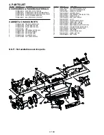
4
−
3. ADJUSTMENT
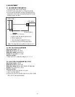
3-1. ADJUSTMENT PREPARATION
1. Use the 3,200K viewer for the subject.
2. Set the ITE gray scale chart II (
γ
=0.45) to the viewer.
3. Set the angle of adjustment control (VR) before starting
adjustment at the center or temporary adjustment (nearly
adjusted) unless specified.
3-2. PCO VOLTAGE ADJUSTMENT
Adjustment location:
VL101
Measuring location:
T102 (PCO)
Measuring equipment:
Multimeter
Subject:
No designation, L-L mode
Adjusting method:
1. Adjust with VL101 so that the voltage is 2.1
±
0.1 V.
3-3. AGC LEVEL ADJUSTMENT (BLC OFF)
Adjustment location:
VR102
Measuring location:
VIDEO OUT
Measuring equipment:
Waveform Monitor (Oscilloscope)
Subject:
Gray scale chart (
γ
=0.45)
Adjusting method:
1. Display the gray scale chart on full screen.
2. Open iris of lens to MAX.
3. Adjust with VR102 so that the video level is 105
±
5 IRE
(750
±
50 mV) during video output.
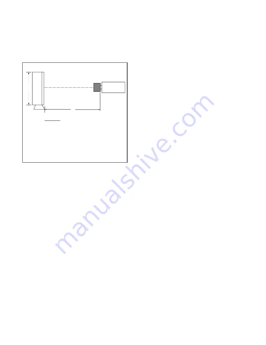
L: Distance from CS mount to pattern (mm)
H: Pattern height (mm)
f : Lens focal length (standard 12.5 mm)
h: Height (4.8 mm) of CCD imaging surface
Note
: The video monitor should be an under-scan TV.
L =
X f
−
12.5 mm
(H + h)
2
H X h
L
CS mount surface
CCD camera
3,200 K viewer
H


