background image

SETTINGS

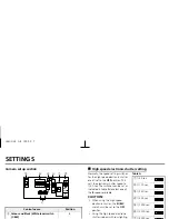
White balance adjustment

Normally the 

WB

 (white balance) switch is set

to the 

A

 (automatic) position and the white

balance is adjusted automatically. If a manual
white balance adjustment is necessary, follow
the steps below.

Set the 

WB

 switch to the 

M

 (manual) position,

then adjust the colour.

Turn 

R

 (VR303) to set the red ratio and/or

B

 (VR302) to set the blue ratio.

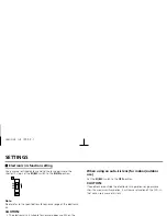
Lens iris adjustment

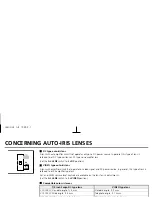
If using a DC type auto-iris lens, you will need
to set the 

LEVEL

 (VR301) volume when

shooting in the conditions described below.

L (counterclockwise):

To decrease the contrast

H (clockwise):

To increase the contrast

If shooting simultaneously in a dark room and through a bright
window.

If the subject background is extremely bright or dark.

If the brightness of the picture on the monitor is not correct.

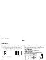
Backlight compensation setting

Use an auto-iris lens and set the 

EI/BLC

 switch

to the 

BLC-ON

 position, to engage the

backlight compensation function.

If using a VIDEO type auto-iris lens

The 

ALC

 volume on the lens should be

turned all the way to 

Av

 (Average).

If the backlight compensation function does
not compensate properly for the conditions, set using the 

LEVEL

volume on the lens.

CAUTION:

The electronic iris function and the backlight compensation function
cannot operate simultaneously.

WB

A

M

VR302

B

R

VR303

LEVEL

L

H

VR301

ON

OFF

ON

BLC

EI

L53U2/XE  GB  1999, 9, 7

English

 11

Summary of Contents for VCC-4372P

Page 1: ...INSTRUCTION MANUAL BEDIENUNGSANLEITUNG MANUEL D INSTRUCTIONS VCC 4372P COLOUR CCD camera CCD Farbkamera Caméra CCD COULEUR CCD L53U2 XE GB 1999 9 7 ...

Page 2: ...tched automatically to colour image or black and white image according to the subject brightness Built in interline transfer method 1 3 CCD approx 470 000 picture elements Low smear anti blooming low lag no burning and no geometric distortion using the CCD solid state image device 100 solid state components giving excellent immunity to shock and vibration Not subject to interference from magnetic ...

Page 3: ...inside it could cause a fire short circuits or damages If water or a liquid gets inside the camera disconnect the power cord Protect from humidity and dust To prevent damages to the camera do not install it where there is greasy smoke or steam where the dampness may get too high or where there is a lot of dust Protect from high temperatures Do not install close to stoves or other heat generating d...

Page 4: ...DEO IN connector 3 Control terminal CONTROL Manual colour black and white setting G ground terminal C colour terminal B black and white terminal 4 External sync composite video signal input connector VBS IN BNC type Connect to this connector the synchronizing signal output from a synchronizing signal device or the composite signal of a video distributor 1 4 5 2 NC GC B 3 L53U2 XE GB 1999 9 7 ...

Page 5: ...nge back adjustment lever See page 6 G Camera installation bracket The bracket can be fixed at the top or bottom of the camera When fixing the bracket be sure to use the longer screws and install the shorter screws on the opposite side to seal the openings 1 Shorter screws M3 x 4 2 Longer screws M3 x 6 3 Camera mounting screw hole 1 4 20 UNC 1 2 3 2 1 G 9 8 F L53U2 XE GB 1999 9 7 ...

Page 6: ...ens with amplifier circuit that operates on video signal and DC power source In general this type of lens is referred to as EE amplifier type lens ALC and LEVEL volume level controls are available on the lens for iris adjustments Set the A I LENS switch to the VIDEO position Compatible auto iris lenses 1 3 inch Sanyo DC type lens VIDEO type lens VCL CS8LY Standard angle f 8 mm Standard angle f 9 m...

Page 7: ... to the maximum telephoto position set the focus using the focus ring on the lens 3 Set the zoom lens to the maximum wide angle position set the focus using the flange back adjustment lever 4 Repeat steps 2 and 3 until the image stays in focus when changing from a telephoto shot to a wide angle shot When the setting is complete tighten the flange back lock screw Note When flange back lock screw is...

Page 8: ...ns mount cap from the camera 2 Install the auto iris lens CS mount type lens Carefully align the lens mount with the camera opening then turn the lens slowly to install it C mount type lens To allow for flange back adjustment install the supplied C mount adaptor on the lens mount then carefully align the lens mount with the camera opening and turn the lens slowly to install it L 1 C mount type len...

Page 9: ...re 2 Install the lens iris plug Solder the cable to the pins following the correct pin layout refer to the table and illustrations then close the plug cover Pin layout DC type lenses VIDEO type lenses 1 Brake coil 12 V DC 50 mA max 2 Brake coil Not used 3 Drive coil Video output 1 0 Vp p high impedance 4 Drive coil Ground for video signal and DC power 1 2 4 3 1 4 3 1 2 2 L53U2 XE GB 1999 9 7 ...

Page 10: ...C IN terminal on the camera Then plug the AC adaptor into an AC outlet The POWER indicator A will light Adjust the picture on the monitor using the Brightness and Contrast controls WARNING This AC adaptor is specially conceived for this camera Never use another type of AC adaptor with this camera and do not use this AC adaptor to power other types of cameras Not for use with toys Never try to disa...

Page 11: ...es can be set as indicated in table A to select one of the 8 speeds available CAUTION When using the high speed electronic shutter the EI BLC switch must be set to the OFF position Using the high speed electronic shutter indoors with low lighting b c d e f g a LEVEL DC VIDEO A I LENS L H VR301 ON OFF ON WB A M BLC EI VR302 B R VR303 C BW L H ON 1 3 2 4 Table A 1 1 50 sec 2 1 120 sec 3 1 250 sec 4 ...

Page 12: ... set the LEVEL VR301 volume when shooting in the conditions described below Backlight compensation setting Use an auto iris lens and set the EI BLC switch to the BLC ON position to engage the backlight compensation function If using a VIDEO type auto iris lens The ALC volume on the lens should be turned all the way to Av Average If the backlight compensation function does not compensate properly f...

Page 13: ...r to the specifications for dynamic range of the electronic iris CAUTION When using an auto iris lens for indoor outdoor use Set the EI BLC switch to the OFF position CAUTION If conditions are outside the electronic iris operation range or more than the maximum illumination it will cause saturation of the CCD In that case use a manual iris lens ON OFF ON BLC EI L53U2 XE GB 1999 9 7 ...

Page 14: ...he brightness Fig 2 H for a brighter setting than L L Standard setting Notes Manual colour black and white setting Connect each pin of the CONTROL terminal as indicated below to set the image to black and white or colour as desired Colour image setting Connect the C colour and the G ground pins Black and white setting Connect the B black and white and the G ground pins CONTROL terminal Image C B H...

Page 15: ...s the voltage correct Are all the signal connecting cables correctly connected Is the lighting sufficient Has the lens cap been removed Is the lens type DC or VIDEO correctly selected Depending on the type of lens the A I LENS switch must be set accordingly Is the iris control correctly set A When using a DC type lens the LEVEL volume inside the camera casing should be adjusted B When using a VIDE...

Page 16: ...More than 48 dB Minimum required illumination incandescent lighting Approx 0 07 lux with a F 1 2 lens B W mode Approx 1 4 lux with a F 1 2 lens Flange back 12 5 mm 0 5 mm White balance ATW Manual switching Lens mount CS mount or C mount with the supplied adaptor Environmental conditions Temperature 10 C 50 C Humidity less than 90 no condensation Power supply 12 V DC Supplied from AC adaptor Power ...

Page 17: ...PECIFICATIONS Dimensions mm Features and specifications are subject to change without prior notice or obligations 136 126 5 1 15 4 25 2 11 1 4 20 UNC 67 54 28 3 100 1 830 1 830 68 62 L53U2 XE GB 1999 9 7 ...

Reviews: