INSTRUCTION MANUAL
VCC-6674
(Warranty attached)
COLOR CCD camera
About this manual
Before installing and using the camera, please read this manual
carefully. Be sure to keep it handy for later reference.
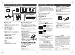
Dimensions: mm
Accessories
Lens iris plug
Safety Guard
This installation should be made by a qualified service person and should
conform to all local codes.
Depending on the conditions of use, installation and
environment, please be sure to make the appropriate settings
and adjustments. If you need help with installation and/or
settings, please consult your dealer.
28
56
45
109
100
0.5
22
11
12
1/4”–20 UNC
INFORMATION TO USER
THIS SYMBOL INDICATES THAT THERE ARE IMPORTANT
OPERATING AND MAINTENANCE INSTRUCTIONS IN THE
LITERATURE ACCOMPANYING THIS UNIT.
WARNING:
TO PREVENT THE RISK OF FIRE OR ELECTRIC SHOCK, DO NOT
EXPOSE THIS APPLIANCE TO RAIN OR MOISTURE.
For the customers in Canada
This Class B digital apparatus complies with Canadian ICES-003.
Pour la clientèle canadienne
Cet appareil numerique de la Classe B est conforme a la norme NMB-003
du Canada.
This equipment has been tested and found to comply with the limits for a Class
B digital device, pursuant to Part 15 of the FCC Rules.
These limits are designed to provide reasonable protection against harmful
interference in a residential installation. This equipment generates, uses, and
can radiate radio frequency energy and, if not installed and used in accordance
with the instructions, may cause harmful interference to radio communications.
However, there is no guarantee that interference will not occur in a particular
installation. If this equipment does cause harmful interference to radio or
television reception, which can be determined by turning the equipment off and
on, the user is encouraged to try to correct the interference by one or more of
the following measures:
Reorient or relocate the receiving antenna.
Increase the separation between the equipment and receiver.
Connect the equipment into an outlet on a circuit different from that to which
the receiver is connected.
Consult the dealer or an experienced radio/TV technician for help.
This device complies with Part 15 of the FCC Rules. Operation is subject to the
following two conditions: (1) This device may not cause harmful interference,
and (2) this device must accept any interference received, including interference
that may cause undesired operation.
Changes or modifications not expressly approved by
Sanyo
may void the user's
authority to operate this camera.
J
In case of problem
Do not use the camera if smoke or strange odors come from the
unit, or if it seems not to function correctly. Disconnect the power
cord immediately, and consult your dealer or a Sanyo Authorized
Service Center.
J
Do not open or modify
Do not open the cabinet, as it may be dangerous and cause
damage to the unit. For internal settings and repairs, consult your
dealer or a Sanyo Authorized Service Center.
J
Do not put objects inside the unit
Make sure that no metal objects or flammable substances get
inside the camera. If used with a foreign object inside, it could
cause fire, short-circuits or damage. If water or liquid gets inside the
camera, disconnect the power cord immediately, and consult your
dealer or a Sanyo Authorized Service Center. Be careful to protect
the camera from rain, sea water, etc.
J
Be careful when handling the unit
To prevent damage, do not drop the camera or subject it to strong
shock or vibration.
J
Install away from electric or magnetic fields
If installed close to a TV, radio transmitter, magnet, electric motor,
transformer, or audio speakers, the magnetic field they generate
will distort the image.
J
Protect from humidity and dust
To prevent damage to the camera, do not install it where there is
greasy smoke or steam, where humidity may get too high, or where
there is a lot of dust.
J
Protect from high temperatures
Do not install close to stoves, or other heat generating devices,
such as spotlights, or where it could be subject to direct sunlight, as
that could cause deformation, discoloration or other damage.
Be careful when installing close to the ceiling, in a kitchen or boiler
room, as the temperature may rise to high levels. Install where the
temperature range will stay between -10
°
C (14
°
F) and 50
°
C
(122
°
F). (no condensation)
J
Cleaning
Dirt can be removed from the cabinet by wiping it with a soft cloth.
To remove stains, use a soft cloth moistened with a soft detergent
solution and wrung dry, then dry by wiping with a soft dry cloth.
Do not use benzine, thinner or other chemical products on the
cabinet, as they may cause deformation and paint peeling. Before
using a chemical cloth, make sure to read all accompanying
instructions. Make sure that no plastic or rubber material comes
in contact with the cabinet for extended periods, as that may
cause damage or paint peeling.
Printed on recycled paper
1AC6P1P2713--
L53X4/US3 (0308TR-SY)
PRECAUTIONS
SANYO Electric Co., Ltd.
Printed in Japan
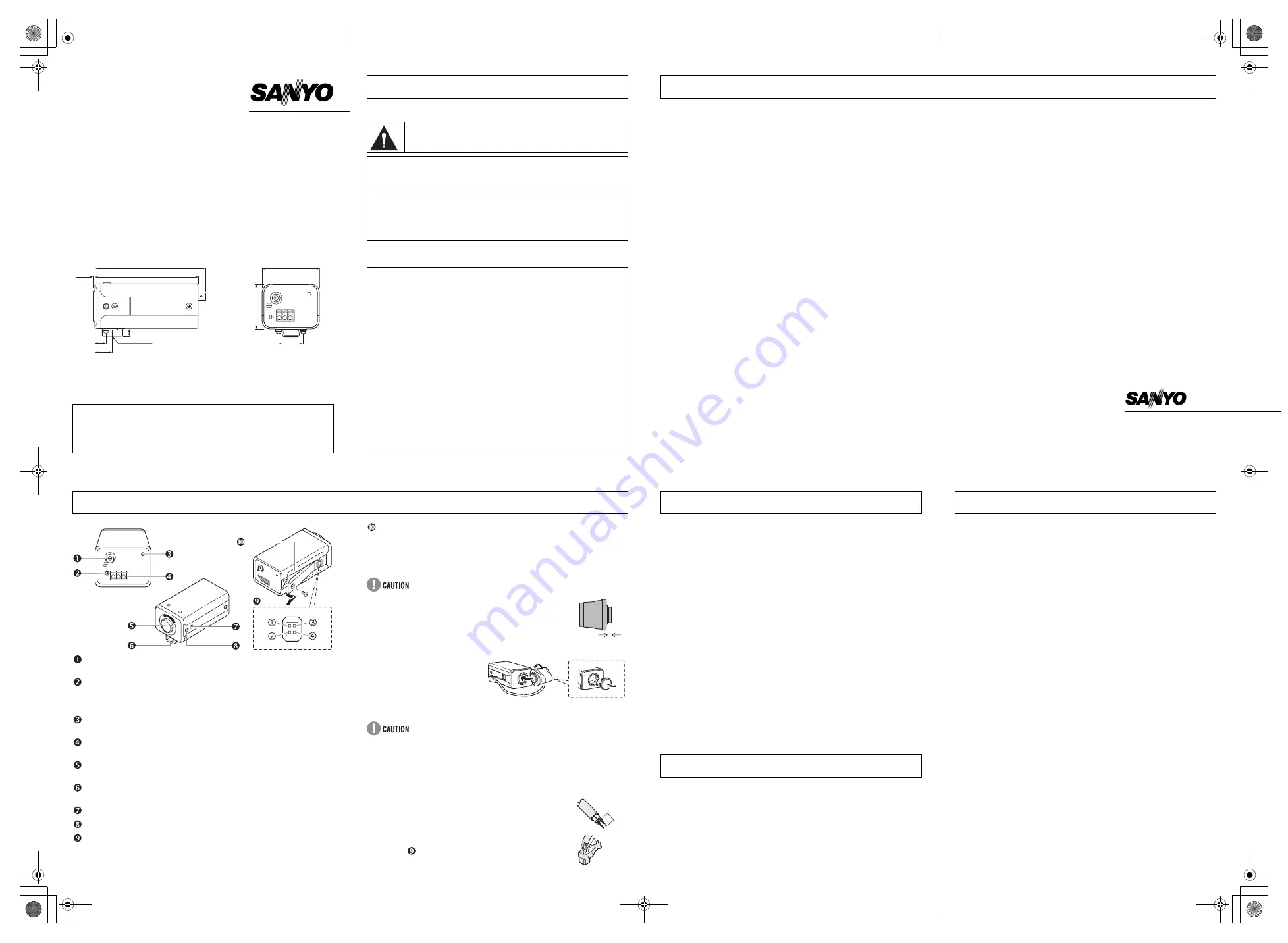
VIDEO OUT (video output terminal: BNC connector)
Connects to the VIDEO IN (video input) terminal on the VCR or monitor.
LINE PHASE (Line phase adjustment volume)
When using two cameras or more, the image on the monitor may roll
vertically when switching sources. This rolling can be minimized by turning
this volume.
POWER (power indicator)
Lights when the camera power is ON.
GND, AC24V, DC12V (ground terminal, 24V AC or 12V DC input
terminal)
Lens cap
Protects the lens from damage.
Camera attachment bracket
Used to attach the camera.
Flange-back lock screw
Flange-back adjustment screw
LENS (lens iris output terminal)
Used to connect the lens plug when the lens is attached.
c
Brake coil (-)
d
Brake coil (+)
e
Drive coil (+)
f
Drive coil (-)
Camera adjustment/setting panel
Contains camera adjustment dials and setting switches.
Q
Attaching the lens
Use a DC type auto-iris lens (sold separately).
Do not use a lens if length “L” is more than 5 mm.
Otherwise, it may damage the camera and prevent
proper installation.
When attaching a C mount lens, attach the lens to the
camera after inserting the C mount ring (option).
1
Remove the lens mount
cap from the camera.
2
Install the auto-iris lens.
3
Connect the lens plug to
the lens iris output
connector (LENS) on the
side of the camera.
When using lenses from other manufacturers, the plug shape may not
correspond to the terminal on the camera. In such a case, remove the
original plug and using a soldering iron, connect the supplied lens iris plug
according to the diagram.
Q
Rewiring the lens cable in the lens iris plug
1
Prepare the lens cable.
Cut the cable at the plug, then remove approx. 8 mm of
the cable sheath and strip about 2 mm from each wire.
2
Install the lens iris plug.
Solder the cable to the pins following the correct pin
layout (
), then close the plug cover.
NAMES AND FUNCTIONS OF PARTS
L
1
2
CS mount type lens
3
2mm
Before sending the camera out for repair, check the items below.
If the problem persists after checking these items, contact your
place of purchase or a Sanyo Authorized Service Center.
J
If no image appears
Is the coaxial cable attached securely?
Are the power and voltage normal?
Has the iris of the lens inside the camera been adjusted correctly
(with the iris dial)?
Is there adequate illumination?
J
If the image is unclear
Is the monitor adjusted correctly?
Is the flange-back position correctly set?
Is the lens in focus?
Is the lens dirty?
Dirt or fingerprints on the lens can adversely affect the image.
Gently wipe any dirt or fingerprints off the lens with a soft cloth or
lens cleaning paper and cleaning fluid (commercially available).
The camera is a precision instrument. Handle it carefully and
always follow the safety precautions. If the camera requires service,
never try to repair it yourself or open the casing.
For servicing, maintenance, or repairs, contact your place of
purchase or a Sanyo Authorized Service Center.
Features and specifications are subject to change without prior notice or
obligations.
TROUBLESHOOTING
SERVICE
SPECIFICATIONS
Scanning system
: NTSC standard TV system
(525 TV lines, 30 frames/sec.)
Interlace
: PLL 2:1 interlace
Image device
: 1/3 inch solid state image device CCD
Picture elements
: 816 (H) x 494 (V)
Effective picture
elements
: 771 (H) x 492 (V)
Synchronizing system : Internal sync, Line lock manually switchable
Resolution
: 520 TV lines horizontally, 350 TV lines vertically
Video output level
: 1.0 Vp-p/75 ohms, composite
Video S/N ratio
: More than 48 dB
Minimum required
illumination
(incandescent lighting)
: Approx. 0.6 lux with a F 1.2 lens (at Gain up: HI)
Approx. 1.2 lux with a F 1.2 lens (at Gain up: NORM)
Backlight
compensation
: Manual MULT/CENT/OFF switching,
MULT: Multi-spot metering system
CENT: Center-weighted metering system
(Active when using an auto-iris lens)
Iris function
: Manual EI/AI switching
Auto-iris lens output
: DC output (variable DC level), 4-pin terminal
Electronic iris range
: 0.6 lux to 30000 lux (F 1.2, lens: Gain up: HI)
1.2 lux to 60000 lux (F 1.2, lens: Gain up: NORM)
Flange-back
: 12.5 mm ±0.5 mm
White balance
: ATW/Manual switching
Gain up
: HI (high)/ NORM (Normal) switching
Lens mount
: CS mount
Environmental
conditions
: Temperature: -10°C – +50°C
Humidity: less than 90% (no condensation)
Power supply
: 12 VDC/24 VAC, 60 Hz
Power consumption
: 3.6 W (with auto iris lens)
Weight
: Approx. 310 g (without lens)
e_l53x4_us3_6.fm Page 1 Wednesday, July 30, 2003 11:30 AM


