background image

USING THE MENU SCREEN

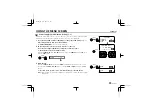
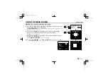
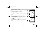
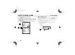
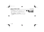
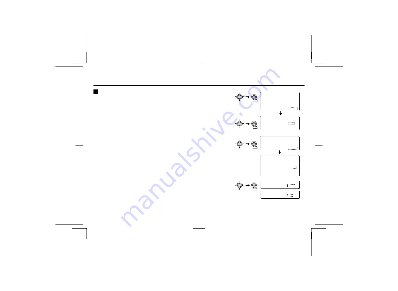
WHITE BALANCE/AWC

B

Push-lock white balance adjustment (AWC)

1

Press the CURSOR (

l

, then 

d

 or 

c

) button to change the WHITE BALANCE setting

to “AWC” (the setting will flash), then press the SET button.

The 

ADJUSTMENT FOR AWC

 screen will be displayed.

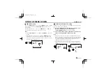
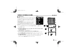
2

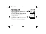
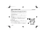
Press and hold the SET button.

While the 

SET

 button is pressed, 

LOCK

 will light steadily, and white balance adjustment

begins. When you release the 

SET

 button, adjustment will stop and 

LOCK

 will begin

flashing.

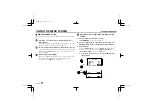
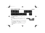
3

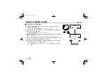
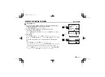
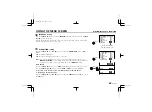
To make  fine adjustments to the tint, press the CURSOR (

l

) button to select the

GO TO MWB setting “SET” (the setting will flash), then press the SET button.

The 

ADJUSTMENT FOR MWB

 screen will then be displayed. Refer to the manual white

balance (MWB) adjustment procedure for details on how to adjust this setting.

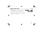
Returning to the default setting

Press the 

CURSOR

 (

l

, then 

d

 or 

c

) button to change the 

PRESET

 setting to 

ON

, then

press the 

SET

 button.

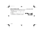
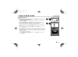
4

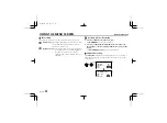
When finished:

Press the 

CURSOR

 (

l

) button to select 

BACK

 (it will flash) at the bottom of the screen.

Then press the 

CURSOR

 (

d

 or 

c

) button to change 

BACK

 to 

END

, and press the 

SET

button.

To return to the previous screen, select BACK then press the SET button.

      MAIN MENU

LANGUAGE        SET  p
CAMERA ID       OFF
SYNC            INT
IRIS            AI   p
WHITE BALANCE   AWC  p

 ADJUSTMENT FOR AWC

AWC LOCK        LOCK

GO TO MWB       SET  p

SET

CURSOR

SET

CURSOR

 ADJUSTMENT FOR AWC

AWC LOCK        LOCK

GO TO MWB       SET  p

SET

CURSOR

 ADJUSTMENT FOR MWB

      [OFFSET]

 R í--ú---z------ü 64

 B í--ú---z------ü 64

MENU            BACK

CURSOR

SET

MENU            END

L53R2/XE  GB  2000, 3, 31

30 

English

Summary of Contents for VCC-6975

Page 1: ...sure to keep it handy for later reference Über diese Bedienungsanleitung Lesen Sie bitte vor der Montage und dem Inbetriebnehmen der Kamera zuerst diese Bedienungsanleitung sorgfältig durch und bewahren Sie sie zum späteren Nachschlagen auf A propos de ce manuel Avant d installer et d utiliser la caméra veuillez lire ce manuel attentivement Gardez le à portée de main pour toute référence ultérieur...

Page 2: ...tting 32 A For SHORT mode 33 B For LONG mode 34 MOTION setting 35 A DIRECTION setting 37 B SIZE setting 38 C MASKING setting 40 D SENSITIVITY setting 42 E ZOOM setting 43 F INTERVAL setting 44 G ALARM SIGN setting 44 Motion detector setting example 45 OPTION settings 48 A APERTURE setting 49 B AGC setting 50 C GAMMA setting 50 D ZOOM setting 51 E MIRROR setting 55 F RS 485 setting 55 G INITIAL set...

Page 3: ...io speakers the magnetic field they generate will distort the image Protect from humidity and dust To prevent damages to the camera do not install it where there is greasy smoke or steam where the dampness may get too high or where there is a lot of dust Protect from high temperatures Do not install close to stoves or other heat generating devices such as spotlights etc or where it could be subjec...

Page 4: ...itor or VCR is connected to this connector 1 Y signal ground 2 C signal ground 3 Y signal 1 0 Vp p 75 ohms unbalanced negative sync 4 C signal 0 3 Vp p 75 ohms unbalanced 5 RS 485 control push lock terminal RS485 G B A A Twisted pair cable terminal B Twisted pair cable terminal G Ground terminal 6 External sync composite video signal input connector VBS IN BNC type Connect to this connector the sy...

Page 5: ...end the DC control signal and power supply to an auto iris type lens F Menu setting button SET Connect the camera to the monitor then press the SET button for about 3 seconds to display the on screen menu G Cursor button CURSOR j Press this button to move the cursor up c Press this button to move the cursor to the right or to turn the settings ON OFF etc d Press this button to move the cursor to t...

Page 6: ...llation bracket The bracket can be fixed at the top or bottom of the camera When fixing the bracket be sure to use the longer screws and install the shorter screws on the opposite side to seal the openings 1 Shorter screws M3 x 4 2 Longer screws M3 x 6 3 Camera mounting screw hole 1 4 20 UNC CAUTION When installing the camera bracket select a location that can support the total weight of the camer...

Page 7: ...ols are available on the lens for iris adjustments Set the A I LENS switch to the VIDEO position Compatible auto iris lenses 1 3 inch Sanyo DC type lens VIDEO type lens VCL CS8LY Standard angle f 8 mm Standard angle f 9 mm VCL CS4LY Wide angle f 4 mm Telephoto angle f 12 mm VCL CS2LY Ultra wide angle f 2 8 mm Greater telephoto angle f 16 mm If using a VIDEO type auto iris lens Set the ALC and LEVE...

Page 8: ...e lens mount then carefully align the lens mount with the camera opening and turn the lens slowly to install it 3 Connect the lens plug to the lens iris output connector LENS on the side of the camera When using lenses from other makers the plug shape may not correspond to the terminal on the camera In such a case remove the original plug and using a soldering iron connect the supplied lens iris p...

Page 9: ...t If the pick up surface is not correctly positioned with relation to the lens focal point the picture will be out of focus in particular when using auto iris power zoom lenses sold separately If that is the case adjust the flange back position as described below 1 Using a screwdriver loosen the FLANGE BACK LOCK screw M2 2 Set the zoom lens to the maximum telephoto position set the focus using the...

Page 10: ...th connector Fig 1 When using a DC 12 V power supply make the connections as indicated in Fig 2 CAUTION To prevent camera and or power supply failure pay close attention to polarity when making the connections 3 Insert the plug of this power supply into a wall outlet The POWER indicator A will light Adjust the picture on the monitor using the Brightness and Contrast controls CAUTION Please use a m...

Page 11: ...on While the menus are being set noise sent on the lines by peripheral devices may cause the settings to change In such a case turn the power off then on again Camera control unit connections This camera main MENU can be set remotely using a camera control unit VAC 60 sold separately connected between the camera and its peripheral devices such as a multiplexer a timelapse VCR a monitor TV etc For ...

Page 12: ...nal Connection to a multiplexer Make the connection between the RS485 A B G terminal on this unit and the multiplexer control terminals A B C NOTE When using devices with an RS 485 connector the supplied clamping cores A must be installed on the three transmission cables to prevent electromagnetic interference from the other connected devices Monitor Timelapse VCR CAMERA IN terminal RS485 control ...

Page 13: ...s the CURSOR c button to move the cursor to the right This button is also used to change ON OFF settings etc 4 Press the CURSOR d button to move the cursor to the left This button is also used to change ON OFF settings etc Switching to sub menu screens Press the CURSOR j l d or c button until an item with a c next to it is flashing then press the SET button Switching to the MAIN MENU screen Press ...

Page 14: ...S item setting to AI mode When the OPTION MENU screen ZOOM or MIRROR items are being used the following items setting screens will not be zoomed in or mirrored The BLC setting screen The ADJUSTMENT FOR MOTION screen SIZE and MASKING setting screens The WHITE BALANCE item ATW MASKING screen If the OPTION MENU screen AGC item is set to OFF and the IRIS mode SENSE UP setting is used setting other tha...

Page 15: ...language then press the SET button The screen displays will change to the language selected 4 When finished Press the CURSOR l button to select BACK it will flash at the bottom of the screen Then press the CURSOR d or c button to change BACK to END and press the SET button MAIN MENU LANGUAGE SET p CAMERA ID OFF SYNC INT LANGUAGE LANGUAGE ENGLISH LANGUE FRENCH SPRACHE GERMANY SET SET CURSOR LANGUE ...

Page 16: ...N is flashing then press the SET button 3 Press the CURSOR l or c button until 1 is flashing then press the SET button Determining the start position for character input Press the CURSOR l button until 2 is flashing then press the CURSOR d or c button until the 2 is pointing to the start position Select the characters using the CURSOR buttons Changing the camera ID to a new ID Press the CURSOR l t...

Page 17: ...A ID SETTING screen NOTE If the CAMERA ID is reset using the menu PRESET setting its position will also be reset to the default position right bottom corner 6 When finished Press the CURSOR l button to select BACK it will flash at the bottom of the screen Then press the CURSOR d or c button to change BACK to END and press the SET button To return to the previous screen select BACK then press the S...

Page 18: ...es the camera s sync signal with the sync signal from an external source A Internal synchronization setting INT 1 Press the SET button for about 3 seconds The MAIN MENU screen will be displayed 2 Press the CURSOR l then d or c button to change the SYNC setting to INT the setting will flash 3 When finished Press the CURSOR l button until END is flashing at the bottom of the screen then press the SE...

Page 19: ...the vertical sync phase Returning the value to the default setting Press the CURSOR l then d or c button to change the PRESET setting to ON then press the SET button 3 When finished Press the CURSOR l button to select BACK it will flash at the bottom of the screen Then press the CURSOR d or c button to change BACK to END and press the SET button To return to the previous screen select BACK then pr...

Page 20: ...r c button to adjust the horizontal sync phase Note If not using a camera for the output signal use a sync signal generator 4 Press the CURSOR l button until the SC1 sub carrier value is flashing then press the SET button to select the color phase SC1 to SC4 5 Press the CURSOR d or c button to make fine adjustments to the color phase Returning the value to the default setting Press the CURSOR l th...

Page 21: ...ous screen select BACK then press the SET button Note If not using a camera to input the sync signal use a sync signal generator and input the VBS signal from the sync signal generator to the external input Settings such as INT in the SYNC item will change automatically to VBS When adjusting the horizontal sync phase you must use an oscilloscope with a dual trace function MENU BACK CURSOR SET MENU...

Page 22: ...e obtained Refer to page 26 A AI Auto Iris mode setting 1 Press the SET button for about 3 seconds The MAIN MENU screen will be displayed 2 Press the CURSOR l then d or c button to change the IRIS setting to AI the setting will flash then press the SET button The ADJUSTMENT FOR AI screen will be displayed LENS TYPE setting The LENS TYPE setting will automatically change to the mode DC or VIDEO whi...

Page 23: ...t BACK then press the SET button BLC setting The following two types of BLC adjustment can be carried out MULTI multi spot photometry Brighter sections of the background are masked so that they do not affect photometry detection Brighter sections of the background are determined on screen and they are masked so that they are in a position which do not affect the main subject such as a person Note ...

Page 24: ...nce more to clear the mask When doing the MULTI setting the dotted lines shown on the illustration are for clarity only they do not actually appear on screen 3 When all masks have been applied press the CURSOR l button to move the mask cursor to the bottom edge of the screen and continue pressing the CURSOR button for about 3 seconds Returning to the default setting Press the CURSOR l then d or c ...

Page 25: ...d position then press the SET button The SIZE screen will be displayed 3 Press the CURSOR d c j or l button to change the size of the photometry area then press the SET button The BLC WINDOW WEIGHTING screen will be displayed Note When the OPTION MENU screen ZOOM or MIRROR item is being used set to ON the BLC MULTI or EVAL setting screen will not be zoomed in or mirrored ADJUSTMENT FOR AI LENS TYP...

Page 26: ...e If the backlight compensation function does not compensate properly for the conditions correct using the LEVEL volume on the lens Returning the values to the default settings Press the CURSOR l then d or c button to change the PRESET setting to ON then press the SET button 5 When finished Press the CURSOR l button to select BACK it will flash at the bottom of the screen Then press the SET button...

Page 27: ...CURSOR l then d or c button until EI in the IRIS item is flashing then press the SET button The ADJUSTMENT FOR EI screen will be displayed 2 Press the CURSOR l then d or c button to select MULTI or EVAL for the BLC backlight compensation setting Note When the electronic iris function captures a very bright subject such as a light etc the quantity of light entering the lens cannot be adjusted and i...

Page 28: ...justments to the color as desired It can be used when the optimum color reproduction cannot be obtained by using ATW Refer to page 31 A Automatic color temperature tracking setting ATW 1 Press the SET button for about 3 seconds The MAIN MENU screen will be displayed 2 Press the CURSOR l then d or c button to change the WHITE BALANCE setting to ATW the setting will flash 3 When finished Press the C...

Page 29: ... in the top left corner of the screen 3 Press the CURSOR d c j or l button to move the mask cursor to the place where color temperature tracking is not to be carried out then press the SET button Continue pressing the CURSOR and SET buttons to apply masks to other areas Masks can be applied to a maximum of 32 separate sections 4 x 8 Note If you apply a mask to a wrong area by mistake press the SET...

Page 30: ...to the default setting Press the CURSOR l then d or c button to change the PRESET setting to ON then press the SET button 5 When finished Press the CURSOR l button to select BACK it will flash at the bottom of the screen Then press the CURSOR d or c button to change BACK to END and press the SET button To return to the previous screen select BACK then press the SET button MENU BACK CURSOR SET MENU...

Page 31: ...B screen will then be displayed Refer to the manual white balance MWB adjustment procedure for details on how to adjust this setting Returning to the default setting Press the CURSOR l then d or c button to change the PRESET setting to ON then press the SET button 4 When finished Press the CURSOR l button to select BACK it will flash at the bottom of the screen Then press the CURSOR d or c button ...

Page 32: ...Blue stronger Returning to the default setting Press the CURSOR l then d or c button to change the PRESET setting to ON then press the SET button 3 When finished Press the CURSOR l button to select BACK it will flash at the bottom of the screen Then press the CURSOR d or c button to change BACK to END and press the SET button To return to the previous screen select BACK then press the SET button M...

Page 33: ...hich are moving quickly B Long exposure mode LONG This is used for making dark scenes lighter such as when filming at nighttime Note The shutter speed can only be set when IRIS has been set to AI mode manual iris or fixed iris lens When the SENSE UP setting is used setting other than OFF the SHUTTER SPEED cannot be set Also the SHUTTER item setting will be forced to OFF L53R2 XE GB 2000 3 31 32 En...

Page 34: ...ting Press the CURSOR l then d or c button to change the PRESET setting to ON then press the SET button 4 When finished Press the CURSOR l button to select BACK it will flash at the bottom of the screen Then press the CURSOR d or c button to change BACK to END and press the SET button To return to the previous screen select BACK then press the SET button SET CURSOR MENU BACK CURSOR SET MENU END MA...

Page 35: ...o END and press the SET button To return to the previous screen select BACK then press the SET button Note When MOTION is set to ON LONG mode cannot be selected When filming moving subjects the higher the SHUTTER SPEED setting acceleration the more pronounced afterimage will be visible Also when the acceleration is high white dots will be visible on the screen this is due to the CCD characteristic...

Page 36: ...er to the examples given on page 45 Note MOTION settings are not possible if either of the following settings have been made The IRIS SENSE UP mode has been set Refer to page 26 The SHUTTER LONG mode has been set Refer to page 34 Note When the MOTION default setting is OFF movements will not be detected and alarms triggers will not be output When doing the MOTION settings the dotted lines and the ...

Page 37: ...ement detection ZOOM When a doubtful movement is detected the zoom ratio is set to X2 and any further movement is tracked F Alarm interval setting function INTERVAL Sets the amount of time for no output when an alarm is received G Alarm signal setting function ALARM SIGN Causes the camera ID to flash when an alarm signal is detected Note If the whole background is empty detection may not be perfor...

Page 38: ...then press the CURSOR d or c button repeatedly The following display will appear Detection is carried out in the direction indicated by the arrow only OFF Any movement is detected regardless of the direction üü Toward the right íí Toward the left óó Upward ññ Downward MAIN MENU LANGUAGE SET p CAMERA ID OFF SYNC INT IRIS AI p WHITE BALANCE ATW p SHUTTER OFF MOTION ON p SET CURSOR SET ADJUSTMENT FOR...

Page 39: ...n Fig 1 depending on the SIZE setting An alarm is output No alarm is output 1 Press the CURSOR l button to select the SIZE setting SET the setting will flash then press the SET button The MOTION SIZE screen will be displayed 2 The V vertical value is flashing then press the CURSOR c button The size area will increase in the vertical direction and the numeric value will also increase Press the CURS...

Page 40: ... the value will change back automatically to a value of 8 or less The size area will be displayed on the screen for reference but it will not necessarily be in the correct position When the OPTION MENU screen ZOOM or MIRROR item is being used set to ON the ADJUSTMENT FOR MOTION screen SIZE and MASKING items setting screens will not be zoomed in or mirrored If the MOTION SIZE setting is used the ba...

Page 41: ...RSOR button is pressed Press the CURSOR button repeatedly to set the masking area Masks can be applied to a maximum of 64 separate sections 8 x 8 Note If you apply a mask to a wrong area by mistake press the SET button once more to clear the mask 3 When the mask has been applied press the CURSOR l button to move the mask cursor to the bottom edge of the screen and continue pressing the CURSOR butt...

Page 42: ...ton To return to the previous screen select BACK then press the SET button Note When the OPTION MENU screen ZOOM or MIRROR item is being used set to ON the ADJUSTMENT FOR MOTION screen SIZE and MASKING items setting screens will not be zoomed in or mirrored If the MASKING setting is used the backlight correction will not operate with a VIDEO type lens MENU BACK CURSOR SET MENU END L53R2 XE GB 2000...

Page 43: ... avoid incorrect detection caused by electronic noise in a dark picture Press the CURSOR l then d or c button so that the Y LEVEL value is flashing Maximum 10 Set the value to a large to avoid incorrect detection of movement caused by electronic noise from a dark picture Y DIFFER This sets the brightness change level A lower setting will ignore bigger changes in the brightness Press the CURSOR l t...

Page 44: ...not operate as desired When finished Press the CURSOR l button to select BACK it will flash at the bottom of the screen Then press the CURSOR d or c button to change BACK to END and press the SET button To return to the previous screen select BACK then press the SET button E ZOOM setting Press the CURSOR j then d or c button to select the ZOOM setting OFF the setting will flash then press the CURS...

Page 45: ...e length of time that the camera ID flashes is the same as the length of time for the alarm ignore time INTERVAL setting When finished Press the CURSOR l button to select BACK it will flash at the bottom of the screen Then press the CURSOR d or c button to change BACK to END and press the SET button To return to the previous screen select BACK then press the SET button Returning to the default set...

Page 46: ...please proceed as follows There are two setting checking methods using the ADJUSTMENT FOR MOTION screen ZOOM or ALARM SIGN A The image is zoomed in when a movement is detected Set the ZOOM item to 5S When the motion detector senses a movement from a subject on the screen the image is zoomed in B The camera ID flashes on screen when a movement is detected Set the ALARM SIGN item to ON then exit the...

Page 47: ...ponds to 1 64 of the screen area there are 64 8 x 8 squares on the screen The default setting will detect a movement that is sensed in 2 squares simultaneously Note If set to 1 square the detection rate will be the highest any slight movement being detected If set to 2 squares or more movement must be detected simultaneously in all the squares the detection rate will therefore be lower MASKING set...

Page 48: ...d make a setting towards the right Y LEVEL In a dark location if electronic noise causes detection make a setting towards the right Y DIFFER If lights are turned on and off causing brightness changes that should not be detected make a setting towards the right DURATION If fast moving objects such as cars that should not be detected will cross the screen make a setting towards the right SENSITIVITY...

Page 49: ...ations are also available E MIRROR setting The image can be rotated horizontally then vertically or vertically then horizontally F RS 485 setting You can set the communication parameters G INITIAL setting This returns all settings to the factory default settings initial values 1 Press the SET button for about 3 seconds The MAIN MENU screen will be displayed 2 Press the CURSOR l button to select th...

Page 50: ...ical value flashes then correct the outlines in the vertical direction As the value increases the correction amount increases Returning the values to the default settings Press the CURSOR l then d or c button to change the PRESET setting to ON then press the SET button 4 When finished Press the CURSOR l button to select BACK it will flash at the bottom of the screen Then press the CURSOR d or c bu...

Page 51: ...the SENSE UP item is set to ON the item AGC setting will be forced to ON C GAMMA setting 1 Press the CURSOR l then d or c button to change the GAMMA setting to ON or OFF the setting will flash ON 0 45 OFF 1 2 When finished Press the CURSOR l button to select BACK it will flash at the bottom of the screen Then press the CURSOR d or c button to change BACK to END and press the SET button To return t...

Page 52: ...ZOOM 2 Press the CURSOR l button then press the CURSOR d or c button repeatedly The image and the zoom ratio will change together X2 X4 or X8 PANNING Press the CURSOR l button to select the PAN setting LEFT the setting will flash then press and hold the SET button The picture will pan toward the left Press the CURSOR c button to select the PAN setting RIGHT the setting will flash then press and ho...

Page 53: ...n The picture will tilt downward Returning to the default settings Press the CURSOR l then d or c button to change the PRESET setting to ON then press the SET button 3 When finished Press the CURSOR l button to select BACK it will flash at the bottom of the screen Then press the CURSOR d or c button to change BACK to END and press the SET button To return to the previous screen select BACK then pr...

Page 54: ...setting TELE the setting will flash then press and hold the SET button The screen will switch to ZOOM mode PANNING Press the CURSOR l button to select the PAN setting LEFT the setting will flash then press and hold the SET button The picture will pan to the left Press the CURSOR c button to select the PAN setting RIGHT the setting will flash then press and hold the SET button The picture will pan ...

Page 55: ...evious screen select BACK then press the SET button Note The maximum zoom ratio in VAR mode is the current zoom ratio setting in FIX mode When ZOOM in the OPTION MENU has been set to ON the PAN and TILT settings will automatically change to the settings which were last made If the ZOOM item in the OPTION MENU is set to ON while a normal screen is displayed simply press the CURSOR buttons for pan a...

Page 56: ...ect the RS 485 setting SET the setting will flash then press the SET button The MENU FOR RS 485 screen will be displayed 2 Press the CURSOR l button so that the BAUD RATE value is flashing then press the CURSOR d or c button to change the communication speed Note The BAUD RATE setting should be compatible with the transmission speed of the peripheral devices 3 Press the CURSOR l then d or c button...

Page 57: ...tch 1 is the least significant bit LSB and switch 7 the most significant bit MSB Down 0 Up 1 This setting is done according to a binary code 8 To setup the termination only when using the RS 485 connector OFF side down Not terminated ON side up Terminated Returning the values to the default settings Press the CURSOR l then d or c button to change the PRESET setting to ON then press the SET button ...

Page 58: ...ill be returned to the factory defaults 2 When finished Press the CURSOR l button to select BACK it will flash at the bottom of the screen Then press the CURSOR d or c button to change BACK to END and press the SET button To return to the previous screen select BACK then press the SET button CURSOR SET MENU BACK CURSOR SET MENU END OPTION MENU APERTURE ON p AGC ON GAMMA ON ZOOM OFF MIRROR OFF RS 4...

Page 59: ...on to accept the address 5 Press the MENU button The MAIN MENU screen will be displayed Note The CURSOR buttons on the camera correspond to the J q s and t buttons on the controller The SET button on the camera corresponds to the ENTER button on the controller MAIN MENU LANGUAGE SET p CAMERA ID OFF SYNC INT IRIS AI p WHITE BALANCE ATW p SHUTTER OFF MOTION OFF OPTION SET p MENU END 2 1 4 3 L53R2 XE...

Page 60: ... will be set 3 Pan and tilt operations operation in normal screen mode If the electronic zoom mode is set to ON press the J q s or t button The focus will return to the center of the screen when the 0 button is pressed B Iris level operations If using a DC type auto iris lens the iris opening can be controlled If using a video type or manual type auto iris lens no operation can be carried out 1 Le...

Page 61: ...ing has not been changed then the zoom ratio will be set to the factory default setting which is X8 If the MOTION setting is at ON the electronic sensitivity SENSE UP will not operate If the SHUTTER item SHORT and LONG settings default values have not been changed the SHORT setting will be 1 120S and the LONG setting will be X8 D Backlight compensation settings 1 Turning backlight compensation on ...

Page 62: ...YNC PHASE í ú z ü 110 4 IRIS ADJUSTMENT EI p AI p ADJUSTMENT FOR BLC POSITION ADJUSTMENT FOR BLC SIZE BLC WINDOW WEIGHTING TOP 0 BOTTOM 0 LEFT 0 RIGHT 0 CENTER FIX 15 ADJUSTMENT FOR AI LENS TYPE DC BLC OFF SENSE UP OFF IRIS LEVEL í ú z ü 30 EVAL p MULTIp OFF X2 X4 X8 X16 X32 OFF BLC MASKING ADJUSTMENT FOR AI LENS TYPE VIDEO BLC OFF SENSE UP OFF EVAL p OFF OFF ADJUSTMENT FOR BLC POSITION ADJUSTMENT...

Page 63: ...FF ON OFF ON OFF ON p OFF ADJUSTMENT FOR ZOOM MODE FIX ZOOM X2 PAN LEFT RIGHT TILT UP DOWN ADJUSTMENT FOR ZOOM MODE VAR ZOOM WIDE TELE PAN LEFT RIGHT TILT UP DOWN X4 X8 X2 H V HV 19200 OFF MENU FOR RS 485 BAUD RATE 19200 ALARM ON ADDRESS 0 ON OFF OFF ON ADJUSTMENT FOR ATW MASKING OFF 5 WHITE BALANCE SETTING ATW p AWC p ADJUSTMENT FOR AWC AWC LOCK LOCK GO TO MWB SET p MWB ADJUSTMENT FOR MWB OFFSET ...

Page 64: ...e lens the LEVEL volume inside the camera casing should be adjusted B When using a VIDEO type lens the LEVEL volume on the lens should be adjusted The picture is not clear Is the monitor correctly adjusted Is the flange back position correctly set Is the lens focus correctly adjusted Are the lens surfaces clean If there is dust or finger prints on the lens the image quality will deteriorate To cle...

Page 65: ...ectronic iris range 1 4 lux to 70 000 lux F 1 2 lens color mode 2 0 lux to 100 000 lux F 1 4 lens color mode Flange back 12 5 mm 0 5 mm White balance ATW AWC MWB setting Electronic shutter 8 speeds selectable by setting SHORT 1 50 1 120 1 250 1 500 1 1000 1 2000 1 4000 1 10000 sec LONG X1 X2 X4 X8 X16 X32 Electronic sensitivity AUTO OFF up to X32 Electronic zoom ON OFF Continuance up to X8 Fix X2 ...

Page 66: ...SPECIFICATIONS Dimensions mm Features and specifications are subject to change without prior notice or obligations 136 126 5 1 13 22 8 11 1 4 20 UNC 67 54 28 L53R2 XE GB 2000 3 31 English 65 ...

Page 67: ...1 pc The C mount adaptor must be used to be able to install a C mount lens on the camera 2 Lens iris plug 4 pin 1 pc 3 Clamping core A 2 pc 4 Clamping core B 1 pc 5 Clamping core C 1 pc 1 2 3 4 5 5 4 3 3 L53R2 XE GB 2000 3 31 66 English ...

Page 68: ...1AC6P1P2280 L53R2 XE 0400KP NI Sanyo Electric Co Ltd Printed in Japan L53R2 XE GB 2000 3 31 ...

Reviews: