background image

SERVICE MANUAL

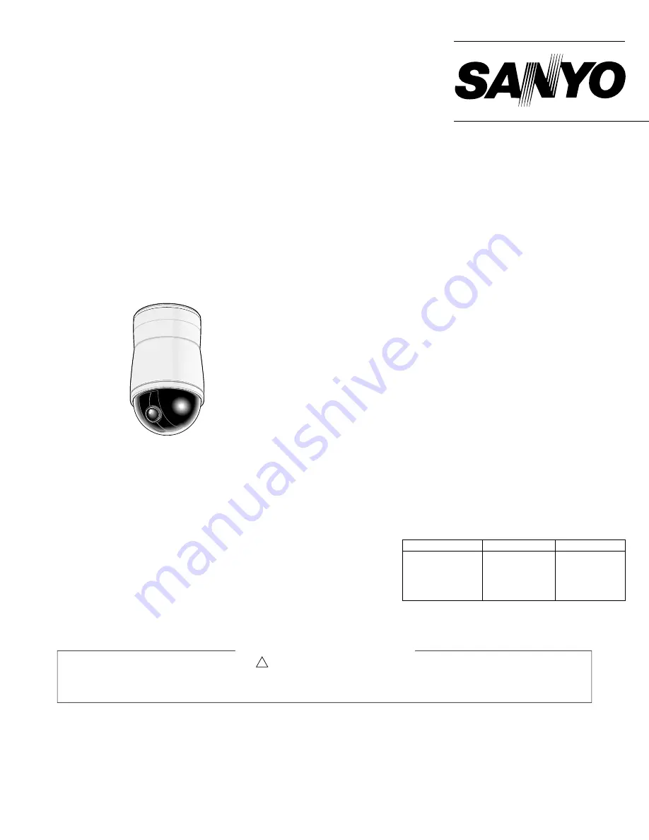
Dome type camera

FILE NO.

REFERENCE No. SM5310480

L5AE4/XE, US

NOTE : 1. Parts order must contain model number, part number, and description.
             2. Substitute parts may be supplied as the service parts.
             3. N. S. P. : Not available as service parts.

Design and specification are subject to change without notice.

The components designated by a symbol (   !   ) in this schematic diagram designates components whose value are of

special significance to product safety. Should any component designated by a symbol need to be replaced, use only the

part designated in the Parts List. Do not deviate from the resistance, wattage, and voltage ratings shown.

PRODUCT SAFETY NOTICE

VCC-9400

(Product Code : 117 119 01)
(U.S.A.)
(Canada)
(Korea)
(Taiwan)

VCC-9400P

(Product Code : 117 119 00)
(Europe)

Please see other materials with Reference number
given in table below.

Materials

Model No.

Reference No.

MM5310481

VCC-9300
VCC-9300P
VCC-9400P
VCC-9400

MECHANISM
SERVICE
TECHNICAL
INFORMATION

CONTENTS

SPECIFICATIONS ...................................2
1. DISASSEMBLY ....................................3
2. POWER BOARD ADJUSTMENT  ........4
3. CAMERA PART ....................................6
4. TROUBLESHOOTING GUIDE ...........10
5. PARTS LIST .......................................15
CIRCUIT DIAGRAM &
PRINTED WIRING BOARDS ................ C1

Summary of Contents for VCC-9400

Page 1: ...d any component designated by a symbol need to be replaced use only the part designated in the Parts List Do not deviate from the resistance wattage and voltage ratings shown PRODUCT SAFETY NOTICE VCC 9400 Product Code 117 119 01 U S A Canada Korea Taiwan VCC 9400P Product Code 117 119 00 Europe Please see other materials with Reference number given in table below Materials Model No Reference No M...

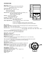
Page 2: ... shutter speed SHORT mode 1 50 VCC 9400P 1 60 VCC 9400 1 100 VCC 9400 1 120 VCC 9400P 1 250 1 500 1 1000 1 2000 1 4000 1 10000 Slow shutter speed LONG mode x2 x4 x8 x16 x32 Electronic sensitivily boosting AUTO OFF works with auto iris Up to x32 max setting possible White balance ATW AWC MWB AGC gain ON OFF MANUAL Motion detector ON OFF individual setting possible Aperture H V setting possible Priv...

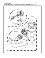
Page 3: ...Y Please refer to BASIC SERVICE TECHNICAL INFORMATION MM5310481 of a separate volume for details BASE unit ROTATION unit MAIN unit MAIN board CAMERA unit POWER board SY 1 board CLEAR DOME INNER COVER CAMERA COVER CASE ...

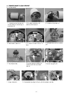
Page 4: ...se unit are separated A power supply is surely shut off 4 Microswitch of base unit 5 A switch is fixed to ON on a tape 6 It attaches base unit on a rotation unit 7 The attached state 8 A power supply is switched on with the switch of a main board pushed 9 A power supply board 1 A tape is removed 2 It incorporates according to the pin which determines a position 4 ...

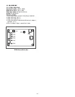
Page 5: ...o designation Adjusting method 1 A connector CN302 is removed and voltage is adjusted 2 Adjust with VR301 to 9 0 V 3 Adjust with VR302 to 5 0 V 4 A connector CN302 is connected and the value of voltage is confirmed 5 5 When a voltage changes readjustment is done POWER board Parts side TP306 TP302 TP301 TP303 TP305 TP304 TP307 VR301 CN301 CN302 VR302 IC301 ...

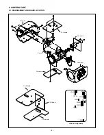
Page 6: ...PART 3 1 DISASSEMBLY AND BOARD LOCATION Cover right CA 3 board Cover left CA 1 board CA 2 board Chassis CA 1 board CA 3 board CA 2 board CT201 TP221 CA 2 board Side B VR203 TP200 CT252 VR202 TP201 TP203 CT202 TP202 ...

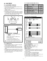
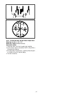
Page 7: ...e size becomes as shown below when performing the adjustment with the gray scale chart ITE gray scale chart γ 0 45 3 2 2 PREPARATION 1 Install the adjustment software VHJ 0150 in a computer running the Windows operating system 2 Use the adjustment commander cable VHJ 0143 to con nect the adjustment commander relay jig VHJ 0142 and CN204 3 Use the adjustment commander relay jig VHJ 0142 to con nect...

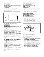
Page 8: ...ct the INT by the key of a keyboard 4 Adjust with TP203 to 17734475 Hz 50 Hz 5 Adjust with CT202 so that the voltage of TP202 is 7 0 V 0 5 V 3 2 8 Frequency Adjustment L L Adjustment location CT201 CA 2 Measuring location TP201 CA 2 Measuring equipment Digital multi meter Subject No designation Adjusting method 1 Select the TRIG and select the L L by the key of a keyboard 2 Adjust with CT201 so th...

Page 9: ...nt method 1 Shield light with a lens cap to provide dark condition 2 Set the camera mode and click the AUTO at the WDD on the adjustment software 3 After completing this adjustment it comfirms that white point can not be seen on the monitor display 4 Click the End button 45 µsec R YL MG Cy G B 75 100 cy g yl mg b U v YL R W ...

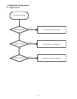
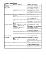
Page 10: ... Judgment of fault The check of a condition Related to the image Related to the mechanism Related to the control Refer to the 4 4 check of mechanism Refer to the 4 3 check of control Refer to the 4 2 check of image YES YES YES NO NO ...

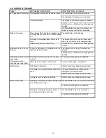
Page 11: ...d and checked Even when he has no dome a focus does not suit A camera is exchanged and confirmed When there is no dome a focus suits A dome is exchanged and checked OSD indicate OSD doesn t indicate it A MAIN board is exchanged and checked It checks compared with OSD currently displayed by the camera block A MAIN board is exchanged and checked A character isn t indicated beautifully A MAIN board i...

Page 12: ...roller is given The check of a setting menu The check of a setting menu The check of a cable A SY 1 board is exchanged and checked The check of a setting menu The check of a cable A SY 1 board is exchanged and checked Operation is impossible with a coaxial controler Although an image comes out it is uncontrollable A switch setup of a base unit is checked An image is sometimes confused The check of...

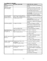
Page 13: ...whether the dome touches the cover A motor is exchanged and checked A belt is exchanged and checked A MAIN board is exchanged and checked An allophone carries out from a fan A fan is exchanged and checked An allophone carries out from a camera A camera is exchanged and confirmed A fan does not rotate A fan is exchanged and checked There is not sound which closed the stopper lever It checks whether...

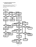
Page 14: ...TP306 5 V TP307 5 V Voltage normality NO NO YES YES Power supply board defect MAIN board exchange Normality MAIN board defect Camera unit exchange Normality YES NO NO Camera unit defect A harness is checked Motor exchange Initializa tion fault Normality NO NO YES YES Motor defect The gap check of Sensor IC and a magnet Other parts defect 4 5 A BASE UNIT AND A MAIN UNIT ARE EX CHANGED AND CHECKED I...

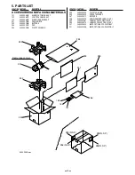
Page 15: ...ON PARTS NO DESCRIPTION LOCATION PARTS NO DESCRIPTION 255 645 060 9299 POLYETHYLENE B 256 645 060 9305 PORYETHYLENE C 257 645 060 9312 BUFFER B 258 645 060 9329 SERIAL NUMBER LABEL N S P 259 645 060 9381 LABEL VCC 9400 ONLY N S P 259 645 060 9374 LABEL VCC 9400P ONLY N S P 261 645 060 9404 INSTROCTIONS VCC 9400 ONLY 261 645 060 9398 INSTROCTIONS VCC 9400P ONLY Dome type camera 9300PACK eps 252 254...

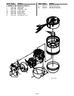
Page 16: ...3 645 060 7813 RH SCR 2 6 3MM 104 645 060 7820 BH SCR 2 4MM 117 645 060 7950 RH M SCR 2 6 4MM 201 645 060 8100 MAIN BOARD ASS Y OLD 201 645 061 7454 MAIN BOARD ASS Y NEW 205 645 060 8131 SENSOR BOARD ASS Y OLD 205 645 061 7461 SENSOR BOARD ASS Y NEW LOCATION PARTS NO DESCRIPTION LOCATION PARTS NO DESCRIPTION 101 117 103 104 201 5 6 102 104 205 9300_03 eps ...

Page 17: ... 21 645 060 7547 SYNCHRO PULLE Y N22 22 645 060 7554 RITINA 23 645 060 7561 T SHAFT 24 645 060 7578 SPACE COLLAR 52 645 060 7677 LOCK NUT 53 645 060 7684 BEARING 54 645 060 7691 SYNCHRO BELT 180 55 645 060 7707 SYNCHRO BELT 140 63 645 060 7783 BINDER 101 645 060 7790 RH SW W SCR 3 10MM 102 645 060 7806 RH SCR 2 6 4MM 103 645 060 7813 RH SCR 2 6 3MM 104 645 060 7820 BH SCR 2 4MM 106 645 060 7844 FH...

Page 18: ...6 3MM 104 645 060 7820 BH SCR 2 4MM 105 645 060 7837 FH SCR 2 12MM 153 645 060 7981 FAN MOTOR ASS Y 204 645 060 8124 I F BOARD ASS Y CABINET AND CHASSIS PARTS 4 1 645 060 7356 CASE 8 645 060 7417 MAGNET BASE 15 645 060 7486 LOCK PLATE 28 645 060 7615 CLEAR DOME 29 645 060 7653 STANDARD LABEL VCC 9400 ONLY N S P 29 645 060 7646 STANDARD LABEL VCC 9400P ONLY N S P 59 645 060 7745 MAGNET BASE 60 645 ...

Page 19: ... DC24V POWER CABLE ASS Y 164 645 060 8094 COMPOUND CABLE ASS Y 202 613 198 6060 COMPL PWB SY 1 SY BOARD ASS Y CABINET AND CHASSIS PARTS 5 2 645 060 7363 BASE 14 645 060 7479 PRESSURE PLATE 16 645 060 7493 STOPPER PLATE 19 645 060 7523 STOPPER 25 645 060 7585 CORD BUSH 26 645 060 7592 PACKING 27 645 060 7608 INSULATION PLATE 29 645 060 7653 STANDARD LABEL VCC 9400 ONLY N S P 29 645 060 7646 STANDAR...

Page 20: ...506 613 199 1712 ASSY UNIT CCD NTSC VCC 9400 ONLY 7507 613 199 2597 COMPL MECHA DN CA1 613 199 0807 COMPL PWB CA 1 CA2 613 199 0760 COMPL PWB CA 2 VCC 9400P ONLY CA2 613 199 0784 COMPL PWB CA 2 VCC 9400 ONLY CA3 613 199 0814 COMPL PWB CA 3 NJ600 411 108 4607 SCR TPG PAN PCS 2X5 NJ610 411 030 5000 SCR BIN 2X3 NJ620 411 109 8901 SCR BIN 2X3 NJ630 411 176 7005 SCR S TPG PAN PCS 1 7X5 0 NJ620 NJ620 60...

Page 21: ...RM188F11H103Z 0 01UF 50V C126 645 060 8766 CC CAP GRM188F11H103Z 0 01UF 50V C127 645 060 8766 CC CAP GRM188F11H103Z 0 01UF 50V C128 645 060 8650 EC CAP MVK50VC1MD55 1UF 50V C129 645 060 8650 EC CAP MVK50VC1MD55 1UF 50V C130 645 060 8650 EC CAP MVK50VC1MD55 1UF 50V C132 645 060 8681 EC CAP MVK6 3VC330MH55 330UF 6 3V C134 645 060 8674 EC CAP MVK6 3VC1000MJ10 1000 6 3V C135 645 060 8643 EC CAP MVY6 3...

Page 22: ...SM3 TB N S P CN302 645 060 8223 CONNECTOR S7B ZR SM3A TF N S P CN303 645 060 8254 CONNECTOR S2B ZR SM3A TF N S P INTEGRATED CIRCUIT IC301 645 060 9220 POWER SUPPLY IC BA9744FV DIODES D301 645 060 9039 DIODE RB161L 40 D302 645 060 9039 DIODE RB161L 40 ZD301 645 060 9046 DIODE PTZ12B ZD302 645 060 9053 DIODE PTZ9 1B INDUCTORS L301 645 060 8995 COILS B953AS 101M 100UFH L302 645 060 8995 COILS B953AS ...

Page 23: ...80P K 50V C0212 403 215 2904 CERAMIC 0 022U K 25V C0213 403 155 1807 CERAMIC 0 01U K 25V C0214 403 283 6309 CERAMIC 1U Z 10V C0215 403 155 1807 CERAMIC 0 01U K 25V C0216 403 365 2601 OS SOLID 22U M 16V C0217 403 357 8109 OS SOLID 22U M 25V C0220 403 155 1807 CERAMIC 0 01U K 25V C0221 403 175 4505 ELECT 47U M 6 3V C0222 403 155 1807 CERAMIC 0 01U K 25V C0223 403 155 1807 CERAMIC 0 01U K 25V C0224 4...

Page 24: ... 0 000 ZA 1 16W R0312 401 105 7909 MT GLAZE 0 000 ZA 1 16W R0313 401 105 7909 MT GLAZE 0 000 ZA 1 16W R0314 401 105 7909 MT GLAZE 0 000 ZA 1 16W SWITCHES S0201 645 053 7776 SWITCH DIP 1P 1TX4 S0202 645 053 7790 SWITCH DIP 1P 1TX8 S0203 645 056 0736 SWITCH SLIDE 2P 2T COMPL PWB CA 1 613 199 0807 COMPL PWB CA 1 SEMICONDUCTORS Q1101 405 045 8200 TR 2SK443 6 TB Q1102 405 079 6302 TR 2SC4399 5 INTEGRAT...

Page 25: ...RYSTAL DEVICES X2001 645 055 5299 OSC CRYSTAL 14 1875MHZ VCC 9400P ONLY X2140 645 049 9821 OSC CERAMIC 20MHZ X2202 645 050 7540 OSC CRYSTAL 14 31818MHZ VCC 9400 ONLY X2501 645 055 5282 OSC CRYSTAL 17 734475MHZ VCC 9400P ONLY VARIABLE RESISTORS VR202 645 000 0270 VR SEMI 47K S OR 645 017 2984 VR SEMI 47K S VR203 645 000 0232 VR SEMI 10K S OR 645 017 2922 VR SEMI 10K S TRIMMERS CT201 645 051 7655 TR...

Page 26: ...09 CERAMIC 0 1U K 10V C2450 403 346 2309 CERAMIC 0 1U K 10V C2501 403 346 2309 CERAMIC 0 1U K 10V VCC 9400P ONLY C2502 403 311 3805 CERAMIC 12P J 50V VCC 9400P ONLY RESISTORS R2001 401 225 8701 MT GLAZE 120K JA 1 16W R2002 401 224 9006 MT GLAZE 10K JA 1 16W R2003 401 225 1702 MT GLAZE 39K JA 1 16W R2004 401 224 9402 MT GLAZE 1 0M JA 1 16W R2005 401 227 5609 MT GLAZE 8 2K JA 1 16W R2006 401 224 890...

Page 27: ...9 401 225 1207 MT GLAZE 4 7K JA 1 16W R2210 401 225 1207 MT GLAZE 4 7K JA 1 16W R2215 401 226 1503 MT GLAZE 0 000 ZA 1 16W R2224 401 224 8900 MT GLAZE 100K JA 1 16W R2226 401 224 8801 MT GLAZE 100 JA 1 16W R2252 401 226 1503 MT GLAZE 0 000 ZA 1 16W R2337 401 226 1503 MT GLAZE 0 000 ZA 1 16W R2338 401 226 1503 MT GLAZE 0 000 ZA 1 16W R2339 401 226 1503 MT GLAZE 0 000 ZA 1 16W R2343 401 225 0309 MT ...

Page 28: ...89 0807 CERAMIC 0 1U K 25V C3403 403 215 0900 CERAMIC 390P J 50V C3404 403 155 1500 CERAMIC 180P J 50V C3405 403 372 4506 CERAMIC 2 2U K 25V C3406 403 372 4506 CERAMIC 2 2U K 25V C3407 403 333 3609 POS SOLID 33U M 10V C3501 403 351 1106 POS SOLID 47U M 16V C3502 403 189 0807 CERAMIC 0 1U K 25V C3503 403 372 4506 CERAMIC 2 2U K 25V C3504 403 009 5708 CERAMIC 100P J 50V C3505 403 189 0807 CERAMIC 0 ...

Page 29: ...Apr 03 SANYO Electric Co Ltd Osaka Japan ...

Reviews: