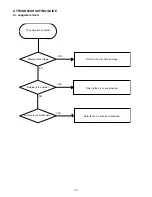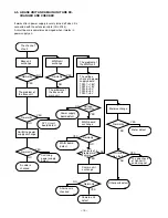
– 8 –
750
±
10 mVp-p
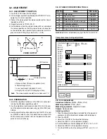
3-2-5. Lens Tracking Adjustment
Adjustment location:
Measuring location:
Measuring equipment:
Monitor display, siemens star chart
Subject:
No designation
Adjusting method:
1. Select the LENS T in the adjustment display.
2. Set the siemens star chart at the position of 940 mm
±
10
mm so that it becomes center of the screen.
3. Click the AUTO button.
4. When AUTO ADJ. NG display, carry out the adjustment again.
3-2-6. Privacy Masking Compensation
Adjustment location:
Measuring location:
Measuring equipment:
Monitor display, privacy masking chart
Subject:
No designation
Adjusting method:
1. Set the privacy masking chart at the position of 940 mm
±
10 mm from the lens.
2. Select the TELE under the LENS T in the adjustment dis-
play. Adjust the field angle so that the center of the privacy
masking chart becomes center of the screen.
3. Operate the LENS X and LENS Y in the adjustment display.
Adjust so that masking is center of the screen.
4. Select the TELE under the LENS Y in the adjustment dis-
play. Confirm that masking is within the limit of the screen.
When the masking is out of the frame, carry out adjustment
again.
3-2-7. Frequency Adjustment (INT)
(VCC-9400P ONLY)
Adjustment location:
CT252, CT202 (CA-2)
Measuring location:
TP203, TP202 (CA-2)
Measuring equipment:
Digital multi meter, Frequency counter
Subject:
No designation
Adjusting method:
1. Click the adjustment software installed from the personal
computer, and the adjustment window will be displayed.
2. Click the START.
3. Select the TRIG, and select the INT by the
← →
key of a
keyboard.
4. Adjust with TP203 to 17734475 Hz
±
50 Hz.
5. Adjust with CT202 so that the voltage of TP202 is 7.0 V
±
0.5 V.
3-2-8. Frequency Adjustment (L-L)
Adjustment location:
CT201 (CA-2)
Measuring location:
TP201 (CA-2)
Measuring equipment:
Digital multi meter
Subject:
No designation
Adjusting method:
1. Select the TRIG, and select the L-L by the
← →
key of a
keyboard.
2. Adjust with CT201 so that the voltage of TP201 is 7.0 V
±
0.5 V.
3. Select the INT by the
← →
key of a keyboard.
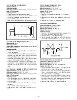
3-2-9. AGC Level Adjustment
Adjustment location:
Computer screen
Measuring location:
VIDEO OUT
Measuring equipment:
Oscilloscope
Subject:
Gray scale chart
Adjusting method:
1. Select the POS1 in the adjustment display, and project the
gray scale at the field angle of below figure.
2. Select the AGC in the adjustment display.
3. Use the computer’s mouse to adjust the AGC in the adjust-
ment window so that the video out terminal is 750
±
10 mVp-p.
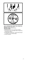
3-2-10. Hue and Chroma Adjustment
Adjustment location:
Computer screen
Measuring location:
VIDEO OUT
Measuring equipment:
Oscilloscope, vectorscope
Subject:
Color bar chart
1. Select POS2 in the adjustment display, and project the color
bar chart at the field angle of below figure.
2. Select the R and B in the adjustment display. Adjust by oper-
ating
← →
key of a keyboard so that the white luminescent
spot is the center of the vectorscope.
3. Select the R GAIN, R HUE, B GAIN and B HUE in the ad-
justment display. Adjust by operating level scroll bar so that
the red and yellow luminescent spots are the size and po-
sition which are designated in the vectorscope.
4. Select the ROM CLEAR in the adjustment display.
siemens star chart
lens
VIDEO OUTPUT
35
µ
sec
940 mm
±
10 mm
camera
viewer


