background image

4

b

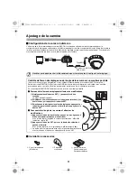
Pour empêcher les interférences

Avec CA 24 V/CC 12 V

Attachez le noyau fourni (petit) aux câbles 
d'entrée/sortie vocale, comme indiqué 
dans la figure.

Attachez le noyau fourni (petit) au câble 
d’alimentation, comme indiqué dans la 
figure.

Attachez le noyau fourni (petit) au câble 
de sortie vidéo, comme indiqué dans la 
figure. 
Attachez le noyau fourni (petit) aux câbles 
d'entrée/sortie de commande, comme 
indiqué dans la figure.

Attachez le noyau fourni (grand) au câble 
LAN, comme indiqué dans la figure.

Avec PoE

Attachez le noyau fourni (petit) aux câbles 
d'entrée/sortie vocale, comme indiqué 
dans la figure.

Attachez le noyau fourni (petit) au câble 
de sortie vidéo, comme indiqué dans la 
figure. 

Attachez le noyau fourni (petit) aux câbles 
d'entrée/sortie de commande, comme 
indiqué dans la figure.
Attachez le noyau fourni (grand) au câble 
LAN, comme indiqué dans la figure.

Câbles d'entrée/

sortie vocale

Câble de sortie 
vidéo

Câbles d'entrée/
sortie de 
commande

Câble 
d’alimentation

Câble LAN

Câble LAN

Câbles

d'entrée/

sortie vocale

Câble de sortie vidéo

Câbles d'entrée/
sortie de commande

L5BQ2_XE(INSTALLATION).book  4 ページ  2006年8月28日 月曜日 午後4時1分

Summary of Contents for VCC-N6695P

Page 1: ... approximately 1 200 000 times in order to maintain unit performance Motor cables used in mechanical parts gears etc Ceiling Installed see page 5 Wall Installed see page 7 In ceiling routing Surface routing In wall routing Surface routing Important Be careful when opening holes for installing the unit Work with the power and video cables pulled out for easy installation Make sure to properly perfo...

Page 2: ...l as the speaker volume For speakers on the camera side use speakers with built in amplifier bConnection when Using PoE Power over Ethernet Power Supply 1 Connect the camera to the LAN through a power adapter and switching hub using LAN cables straight type Video output BNC connector Voice output black 3 5 φ mini jack External microphone input white 3 5 φ mini jack Microphone Speaker TV monitor Sw...

Page 3: ...nnector Voice output black 3 5 φ mini jack External microphone input white 3 5 φ mini jack Microphone Speaker TV monitor PC LAN cable straight type Max 100 m Video voice data Power supply Microphone Speaker Voice signal transmission to camera Voice signal check at PC LAN cable straight type Max 100 m Switching hub with PoE support L5BQ2_XE INSTALLATION book 2 ページ 2006年8月28日 月曜日 午後4時1分 ...

Page 4: ...t to the router IP address on the LAN side Camera IP address default 192 168 0 2 Port number on the LAN side Camera video port number default 80 Port number on the WAN side Optional For communication use TCP IP Voice port number Conduct the following port forwarding settings with respect to the router IP address on the LAN side Camera IP address default 192 168 0 2 Port number on the LAN side Came...

Page 5: ...ore large to the LAN cable as shown in the figure With PoE Attach the 1 supplied core small to the voice input output cables as shown in the figure Attach the 1 supplied core small to the video output cable as shown in the figure Attach the 1 supplied core small to the control input output cables as shown in the figure Attach the 1 supplied core large to the LAN cable as shown in the figure Power ...

Page 6: ... page 9 Pass the LAN cable through the camera in order to plug it into the LAN port on the network board after removing the dome cover See step 3 under 5 Remove the dome cover on page 6 Aligning the ribs C and hook D on the camera unit with the slot on the base plate push the camera unit until it clicks 1 Remove the base plate from the camera unit 2 Install the base plate Make sure to tighten the ...

Page 7: ...ort on the network board b Set up the camera remotely see page 11 b Check the settings screen or camera angle on a portable monitor see page 11 Align the rib marks A and push the dome cover until it clicks Plug the PoE hub into a power outlet 5 Remove the dome cover 6 Adjust Check the video image from the camera E F Push G LAN port 7 Install the dome cover 8 Power on A L5BQ2_XE INSTALLATION book 6...

Page 8: ...er in the arrowed direction 1Push the spring A and set free the hooks from the base chassis Lift and turn the camera in the arrowed directions so that the back of the camera becomes visible 2Rotate the camera so that the position of the locks B is upside down 3Align the locks B with the slots C on the base chassis push the spring A and mount the camera Keep the flat cable away from the chassis 1 R...

Page 9: ...unit to the base plate 6 Adjust Check the video image from the camera 7 Install the dome cover D C E 8 Power on When Moving the Camera from Wall to Ceiling 1 Remove the cover sheet being careful not to distort it 2 Free the locks G on the base chassis 3 Push the spring and release the camera 4 Mount the camera by following the opposite procedure from that indicated in 4 Change the camera position ...

Page 10: ...ce between devices is short but not in duct or aerial routing Cable type Length RG 59U 3C 2V 250 m max RG 6U 5C 2V 500 m max RG 11U 7C 2V 600 m max AL OUT COMMON AL IN1 AL IN2 AC 24 V DC 12 V GND AC 24 V DC 12 V Do not connect the power cord until all other connections have been completed Speaker connection Microphone connection Black Speaker cable White Microphone cable LAN cable Non PoE power su...

Page 11: ...nput 2 2 is selected Alarm input signal Alarm input signal Alarm Signal Input If a lamp is connected to this cable it will light up when an alarm signal is received or when the built in motion sensor detects movement Alarm Signal Output b With AC 24 V Power Supply Connection b With DC 12 V Check that polarity is correct For the connections use cables thicker than 18 AWG For the connections use cab...

Page 12: ...cking A dedicated MONITOR OUT connector is provided for portable monitors b To check the settings screen and make changes 1 Hold down the SET button 1 for over a second The main menu appears 2 Select a menu by pressing the Select button 2 up and down then press the SET button 3 Select the setting item and value by pressing the Select button left and right b To check the camera angle and make chang...

Page 13: ...pproximativement 1 200 000 utilisations pour conserver la performance de l appareil Moteur câbles utilisés dans les pièces mécaniques engrenages etc Plafond installé voir page 5 Mur installé voir page 7 Câblage dans le plafond Câblage en surface Câblage dans le mur Câblage en surface Important Attention lorsque vous percez des trous pour installer l appareil Travaillez avec les câbles d alimentati...

Page 14: ...ume des haut parleurs Pour les haut parleurs côté caméra utilisez des haut parleurs à amplificateur intégré bBranchement avec la fonction PoE Power over Ethernet alimentation électrique 1 Reliez la caméra au réseau LAN via un adaptateur et un concentrateur de commutation en utilisant des câbles LAN de type droit Sortie vidéo connecteur BNC Sortie vocale noire 3 5 φ mini jack Entrée de microphone e...

Page 15: ...LAN droit Max 100 m Concentrateur de commutationavec prise en charge de la fonction PoE Sortie vidéo connecteur BNC Sortie vocale noire 3 5 φ mini jack Entrée de microphone externe blanche 3 5 φ mini jack Microphone Haut parleur Moniteur TV Microphone Haut parleur Ordinateur personnel Données vidéo vocales alimentation électrique Transmission du signal vocal vers la caméra Contrôle du signal vocal...

Page 16: ...smission par port concernant le routeur Adresse IP côté LAN Adresse IP de la caméra par défaut 192 168 0 2 Numéro de port côté LAN Numéro de port vidéo sur la caméra par défaut 80 Numéro de port côté WAN Optionnel Pour la communication utilisez TCP IP Numéro de port vocal Procédez aux réglages suivants pour la transmission par port concernant le routeur Adresse IP côté LAN Adresse IP de la caméra ...

Page 17: ...AN comme indiqué dans la figure Avec PoE Attachez le noyau fourni petit aux câbles d entrée sortie vocale comme indiqué dans la figure Attachez le noyau fourni petit au câble de sortie vidéo comme indiqué dans la figure Attachez le noyau fourni petit aux câbles d entrée sortie de commande comme indiqué dans la figure Attachez le noyau fourni grand au câble LAN comme indiqué dans la figure Câbles d...

Page 18: ... 9 Faites passer le câble LAN à travers la caméra pour le brancher dans le port LAN de la carte de réseau après avoir enlevé le couvercle du dôme Voir l étape 3 sous 5 Ôtez le couvercle du dôme page 6 Alignez les nervures C et le crochet D du groupe caméra avec la fente de la plaque de base Appuyez sur le groupe caméra jusqu à entendre un clic 1 Enlevez la plaque de base du groupe caméra 2 Install...

Page 19: ...distance voir page 11 b Contrôlez l écran des réglages ou l angle de la caméra sur un moniteur portable voir page 11 Alignez les repères des nervures A et appuyez sur le couvercle du dôme jusqu à entendre un clic Branchez le concentrateur de l alimentation PoE sur une sortie d alimentation 5 Ôtez le couvercle du dôme 6 Ajustez Contrôlez l image vidéo de la caméra E F Pousser G Port LAN 7 Installez...

Page 20: ...a direction indiquée par la flèche 1Poussez le ressort A et débloquez les crochets du châssis de la base Soulevez et tournez la caméra dans la direction de la flèche de manière que l arrière de la caméra devienne visible 2Tournez la caméra de manière que les verrous B soient à l envers 3Alignez les verrous B sur les fentes C du châssis de la base poussez le ressort A et montez la caméra Maintenez ...

Page 21: ...roupe caméra sur la plaque de base 6 Ajustez Contrôlez l image vidéo de la caméra 7 Installez le couvercle du dôme D C E 8 Mise sous tension Lors du déplacement de la caméra du mur au plafond 1 Retirez la plaque de couverture en vous assurant de ne pas la tordre 2 Libérez les verrous G sur le châssis de la base 3 Poussez le ressort et libérez la caméra 4 Montez la caméra en inversant la procédure ...

Page 22: ...ls est courte mais pas dans un câblage dans une gaine ou une antenne Type de câble Longueur RG 59U 3C 2V 250 m maxi RG 6U 5C 2V 500 m maxi RG 11U 7C 2V 600 m maxi AL OUT COMMON AL IN1 AL IN2 AC 24 V DC 12 V GND AC 24 V DC 12 V Ne branchez pas le cordon d alimentation tant que les autres branchements n ont pas ete effectues Noir Câble haut parleurs Blanc Câble microphone Câble LAN COMMON COMMON Bra...

Page 23: ...nexions utilisez des câbles dont l épaisseur supérieure à 18 AWG Pour les connexions utilisez des câbles dont l épaisseur supérieure à 18 AWG Pour les détails voir Spécification de l entrée d alarme dans le MANUEL D INSTRUCTIONS b Avec l entrée d alarme 1 1 est sélectionné Alarme signal d entrée Alarme signal d entrée Entrée du signal d alarme Si un témoin est relié à ce câble il s allume lorsqu u...

Page 24: ... portables b Pour contrôler l écran des réglages et effectuer les modifications 1 Maintenez enfoncé le bouton SET 1 pendant plus d une seconde Le menu principal apparaît 2 Sélectionnez un menu en appuyant sur le bouton de sélection 2 en haut et en bas puis appuyez sur le bouton SET 3 Sélectionnez la rubrique et la valeur de réglage en appuyant sur le bouton de sélection à gauche et à droite puis a...

Page 25: ... empfohlen diese Bauteile ungefähr alle zwei Jahre d h nach ungefähr 1 200 000 Nutzungen auszutauschen Motor in mechanischen Gruppen verwendete Kabel Getriebe usw Deckeninstallation siehe Seite 5 Wandinstallation siehe Seite 7 Unterputzverlegung an der Decke Überputzverlegung Unterputzverlegung an der Wand Überputzverlegung Wichtiger Hinweis Vorsicht bei der Anbringung von Löchern für die Installi...

Page 26: ...arüber hinaus empfiehlt es sich die Empfindlichkeit des Mikrofons und die Lautstärke der Lautsprecher zu regulieren Verwenden Sie Geräte mit eingebautem Verstärker für die Lautsprecher auf der Kameraseite bAnschlussschema für die Stromversorgung mit PoE Power over Ethernet 1 Schließen Sie die Kamera über einen Stromadapter und ein Umschalt Hub mit LAN Kabeln Patchkabeln an das LAN Netzwerk an PC V...

Page 27: ... Patchkabel Max 100 m Mikrofon Lautsprecher LAN Netzwerkkabel Patchkabel Max 100 m Umschalt Hub mit PoE Unterstützung Sprach Ausgang schwarz 3 5 φ Miniklinkenbuchse Externer Mikrofon Eingang weiß 3 5 φ Miniklinkenbuchse Lautsprecher TV Monitor Video Ausgang BNC Stecker Video Sprachdaten Stromversorgung Sprachsignalübertragung an Kamera Sprachsignalüberprüfung am PC Mikrofon L5BQ2_XE INSTALLATION b...

Page 28: ... des Routers aus IP Adresse auf der LAN Seite Kamera IP Adresse Grundeinstellung 192 168 0 2 Port Nummer auf der LAN Seite Kamera Video Port Nummer Grundeinstellung 80 Port Nummer auf der WAN Seite Optional Verwenden Sie für die Kommunikation das TCP IP Protokoll Voice Port Nummer Führen Sie die folgenden Einstellungen für die Port Weiterleitung unter Berücksichtigung des Routers aus IP Adresse au...

Page 29: ...ng gezeigt an dem LAN Kabel anbringen Mit PoE Bringen Sie den 1 mitgelieferten Ferritkern klein wie in der Abbildung gezeigt an den Kabeln für Sprachübertragung empfang an Bringen Sie den 1 mitgelieferten Ferritkern klein wie in der Abbildung gezeigt am Kabel für den Videoausgang an Bringen Sie den 1 mitgelieferten Ferritkern klein wie in der Abbildung gezeigt an den Kabeln für Ein Ausgang der Ste...

Page 30: ...Kuppelabdeckung in den LAN Anschluss an der Netzwerkkarte gesteckt werden kann Vergleiche die Schritte 3 im Abschnitt 5 Die Kuppelabdeckung abnehmen auf Seite 6 Die an der Kameraeinheit angebrachten Rippen C und die Feder D mit dem Schlitz auf der Grundplatte in Übereinstimmung bringen und die Kameraeinheit bis zum Einrasten andrücken 1 Die Grundplatte von der Kamera abnehmen 2 Die Grundplatte ins...

Page 31: ... Kamera mit der Fernsteuerung vornehmen siehe Seite 11 b Einstellbildschirm oder Aufnahmewinkel auf einem tragbaren Monitor überprüfen siehe Seite 11 Rippenkennzeichnung A in Übereinstimmung bringen und die Kuppelabdeckung bis zum hörbaren Einrasten andrücken Das PoE Hub in eine Netzsteckdose einstecken 5 Die Kuppelabdeckung abnehmen E F Drücken G LAN Anschluss 6 Überprüfung und ggf Anpassung der ...

Page 32: ...er A ausüben und die Haken an der Gehäusebasis freigeben Kamera anheben und in Pfeilrichtung drehen bis die Rückseite der Kamera sichtbar wird 2Kamera so drehen dass eine Umkehrung der Position der Arretierungen B erzielt wird 3Die Arretierungen B mit den Schlitzen C an der Gehäusebasis in Übereinstimmung bringen Druck auf die Feder A ausüben und die Kamera montieren Das Flachkabel muss stets vom ...

Page 33: ...instecken 5 Kamera auf der Grundplatte montieren 6 Überprüfung und ggf Anpassung der von der Kamera erzeugten Bildschirmanzeige 7 Montage der Kuppelabdeckung D C E 8 Einschalten Bei Umrüstung von der Wand zur Deckeninstallation der Kamera 1 Nehmen Sie die Deckplatte vorsichtig ab ohne sie zu verbiegen 2 Free the locks G on the base chassis 3 Druck auf die Feder ausüben und die Kamera freisetzen 4 ...

Page 34: ...nd zwischen den Geräten kurz ist aber nicht bei Kabelkanälen oder an Außenwänden verlegten Leitungen Kabeltyp Länge RG 59U 3C 2V max 250 m RG 6U 5C 2V max 500 m RG 11U 7C 2V max 600 m AL OUT AL IN1 AL IN2 AC 24 V DC 12 V GND AC 24 V DC 12 V COMMON COMMON COMMON ohne PoE Stromversorgung Lautsprecheranschluss Mikrofonanschluss Schwarz Lautsprecherkabel Weiss Mikrofonkabel Das Netzkabel nicht anschli...

Page 35: ...arm eingangssignal Alarm eingangssignal Alarmeingangsignal Wenn eine Lampe an dieses Kabel angeschlossen ist leuchtet diese auf wenn ein Alarmsignal empfangen wird oder wenn der eingebaute Bewegungssensor ein bewegtes Objekt erfasst hat Alarmausgangssignal b Mit AC 24 V Netzanschluss b Mit DC 12 V Prüfen Sie ob die Polarität richtig ist Verwenden Sie für die Anschlüsse Kabel mit einem Durchmesser ...

Page 36: ...baren Monitors wird ein spezifischer MONITOR OUT Stecker mitgeliefert b Zur Überprüfung und Anpassung des Einstellbildschirms 1 Halten Sie die SET Taste 1 länger als eine Sekunde gedrückt Das Hauptmenü wird eingeblendet 2 Drücken Sie die Auswahltaste 2 auf oder abwärts um ein Menü auszuwählen und bestätigen dann mit der SET Taste 3 Wählen Sie eine Einstellung indem Sie die Auswahltaste nach rechts...

Page 37: ...件将会磨损并恶化 根 据使用环境而定 建议约每两年 约1 200 000次 更换零件一次 以维护装置的性能 电动机 机械零件中使用的电缆 齿轮等 天花板安装方式 参见第5页 墙壁安装方式 参见第7页 天花板内的布线 表面的布线 墙内的布线 表面的布线 重要事项 请小心掀开安装本机时所使用的孔 为求方 便安装 请使用拉出的电源和视频电缆 请确保要安装本机的天花板或墙壁已经做好 适当的防水处理 请勿将本机安装在表面凹凸不平的位置上 并且安装位置能够承受本机的整体重量 本机的安装环境温度需保持在 10 C到 40 C 之间 不允许有冷凝 为了预防静电产生的损坏 请在触摸本机之 前 先触摸附近的金属物体 如门把等 让身上的静电消散 A B VCC PN9575P English Français Deutsch 中文简体 L5BQ2_XE INSTALLATION book 0 ページ 2006年...

Page 38: ...啸声 同时 请调整一下麦克风的灵敏度及扬声器的音量 对于摄像机上的扬声器 请使用带有内置放大器的扬声器 b使用PoE Power over Ethernet 电源时的连接 1 用 LAN 电缆 直线型 通过电源适配器和交换集线器将摄像机连接到 LAN 备注 可使用具有 PoE 支持功能的多个交换集线器延长传输距离 有关可延长距离的详细信息 请参见 规格中的集线器性能部分等信息 交换集线器 计算机 电源适配器 LAN 电缆 直线型 最大值 100 m LAN 电缆 直线型 到摄像机的语音信号传输 在计算机上进行的语音信号检查 视频输出 BNC 接头 语音输出 黑色 3 5 φ 迷你插孔 外部麦克风输入 白色 3 5 φ 迷你插孔 视频 语音数据 电源 最大值 100 m 扬声器 麦克风 扬声器 麦克风 TV 监视器 L5BQ2_XE INSTALLATION book 1 ページ 2006年...

Page 39: ...oE 支持功能的交换集线器将摄像机连接到 LAN 视频输出 BNC 接头 语音输出 黑色 3 5 φ 迷你插孔 外部麦克风输入 白色 3 5 φ 迷你插孔 扬声器 麦克风 TV 监视器 计算机 到摄像机的语音信号传输 在计算机上进行的语音信号检查 视频 语音数据 电源 扬声器 麦克风 具有 PoE 支持功能的 交换集线器 LAN 电缆 直线型 最大值 100 m LAN 电缆 直线型 最大值 100 m L5BQ2_XE INSTALLATION book 2 ページ 2006年8月28日 月曜日 午後4時1分 ...

Page 40: ...口转发的详细信息 请参见路 由器说明手册 视频端口号 对路由器进行以下端口转发设置 LAN的IP地址 摄像机IP地址 默认值 192 168 0 2 LAN的端口号 摄像机视频端口号 默认值 80 WAN的端口号 可选 要进行通信 请使用 TCP IP 语音端口号 对路由器进行以下端口转发设置 LAN的IP地址 摄像机IP地址 默认值 192 168 0 2 LAN的端口号 摄像机语音端口号 默认值 34341 WAN的端口号 摄像机语音端口号 默认值 34341 要进行通信 请使用UDP 在 LAN 中安装多个摄像机时 请相应地向前更 改第二个摄像机开始的语音端口号 默认值 为 34341 并对相应的路由器进行端口转发设 置 当连接到路由器时 请使用直线型 LAN 电 缆 当连接到ADSL调制解调器或其他设备时 请参阅该设备的说明手册 路由器或 ADSL 调制解调器 Internet L...

Page 41: ...频输出电缆 如图所示 将随附的屏蔽环 小 连接至控 制输入 输出电缆 如图所示 将随附的屏蔽环 大 连接至 LAN 电缆 使用 PoE 如图所示 将随附的屏蔽环 小 连接至语 音输入 输出电缆 如图所示 将随附的屏蔽环 小 连接至视 频输出电缆 如图所示 将随附的屏蔽环 小 连接至控 制输入 输出电缆 如图所示 将随附的屏蔽环 大 连接至 LAN 电缆 电源电缆 LAN电缆 语音输入 输出电缆 视频输出电缆 控制输入 输出电缆 LAN电缆 语音输入 输出电缆 视频输出电缆 控制输入 输出电缆 L5BQ2_XE INSTALLATION book 4 ページ 2006年8月28日 月曜日 午後4時1分 ...

Page 42: ... 等于或小于5 mm 含垫 圈 将过长的连接电缆塞回天花板里 有关连接的详 细信息 请参见第 9 页 在拆卸球罩后 将LAN电缆穿过摄像机 以将其 插入网络板上的LAN端口 请参见第6页的 5 取下球罩 的步骤3 将摄像机装置上的肋 C 与勾子 D 与底座 上的插槽对齐 推动摄像机装置直到发出喀嚓 声 1 卸下摄像机装置底座 2 装上底座 确保已完全拧紧螺钉 如未使用特定大小 的螺钉 很有可能使本机掉落 A B B 2 1 3 连接天花板的电缆 4 将摄像机装置安装在底座上 确保摄像机装置与底座匹配完好 C D 断开 PoE 电源集线器电源 L5BQ2_XE INSTALLATION book 5 ページ 2006年8月28日 月曜日 午後4時1分 ...

Page 43: ...用随附的螺钉 G 将摄像机装置拧紧 3将LAN电缆插入网络板上的LAN端口 b 遥控设置摄像机 参见本安装手册的背面 b 在便携式监视器上检查设定屏幕和摄像机的角 度 参见本安装手册的背面 将肋标记 A 对齐并推动球罩直到发出喀擦 声 将PoE集线器插入电源插座 5 取下球罩 E F 压 G LAN端口 6 调整 查看摄像机视频的图像 7 安装球罩 8 电源开启 A L5BQ2_XE INSTALLATION book 6 ページ 2006年8月28日 月曜日 午後4時1分 ...

Page 44: ...连接的详细信息 请参见第5页的 3 连接天花板的电缆 当按下肋标记 E 对面的机柜部位 F 时 请按箭头方向开启球罩 1按下弹簧 A 并且放开底盘的勾子 将摄 像机拿起并且旋转到箭头所指的方向 以便 看清楚摄像机的背面 2旋转摄像机 直到锁 B 倒立为止 3将锁 B 和底盘上的插槽 C 对齐 按 下弹簧 A 然后安装摄像机 请让扁平电缆远离底盘 1 卸下摄像机装置底座 2 装上底座 确保已完全拧紧螺钉 如未使用特定大小 的螺钉 很有可能使本机掉落 3 取下球罩 B B 2 1 F E 压 4 改变摄像机的位置 A B A C B 断开 PoE 电源集线器电源 L5BQ2_XE INSTALLATION book 7 ページ 2006年8月28日 月曜日 午後4時1分 ...

Page 45: ... 请参见 7 安装球罩 下方的 在天花板上安 装 参见第 6 页 将 PoE 集线器插入电源插座 5 将摄像机装置安装在底座上 6 调整 查看摄像机视频的图像 7 安装球罩 D C E 8 电源开启 把摄像机从墙上移到天花板时 1 小心卸下机盖片 请勿将其扭曲 2 Free the locks G on the base chassis 3 按下弹簧并取下摄像机 4 请按 4 改变摄像机的位置 步骤所示的 相反过程安装摄像机 参见第7页 请检查扁平电缆没有缠绕在底盘之 间 卸下机盖片时 请勿将其扭曲 机 盖片的变形 如机盖片上的大片绉 纹或弯曲 可能会在重新装上机盖 片时使其接触到球罩的内面 这样 会使摄像机无法正常操作 G L5BQ2_XE INSTALLATION book 8 ページ 2006年8月28日 月曜日 午後4時1分 ...

Page 46: ...以使 用RG 59U同轴电缆 但不能在管 线或是天线布线中使用 电缆类型 长度 RG 59U 3C 2V 最长 250 m RG 6U 5C 2V 最长 500 m RG 11U 7C 2V 最长 600 m AL OUT COMMON AL IN1 AL IN2 AC 24 V DC 12 V GND AC 24 V DC 12 V COMMON COMMON 扬声器连接 麦克风连接 黑色 扬声器电缆 白色 麦克风电缆 LAN电缆 非PoE电源 在其它连接尚未完成之前 请勿连接电源线 L5BQ2_XE INSTALLATION book 9 ページ 2006年8月28日 月曜日 午後4時1分 ...

Page 47: ...ENSITIVITY ZOOM uZOOM TIME DURATION ALARM SIGN PRESET MENU 1 y NO OFF SET y SET y OFF 5S 5S OFF OFF BACK GND 有关详细信息 请参见说明手册中的 指定报警输入 b 含报警输入1 选定 1 b 含报警输入2 选定 2 报警输入信号 报警输入信号 报警信号输入 如果此电缆已连接到指示灯 当接收到报警信号或是内置运动传感器检测到运动时 该灯就会亮起 报警信号输出 b 使用AC 24 V 电源线的连接 b 使用DC 12 V 检查正负极性是否正确 请使用比18 AWG粗的电缆进行连接 请使用比18 AWG粗的电缆进行连接 所有连接电缆应是最大长 度不大于 600m 的 24 AWG 或更高级的电 缆 LAN 电缆 请参阅 使用 PoE 电源时的连接 1 与 2 与 不使用 PoE 电源进行的连...

Page 48: ...然后按下SET按钮 3 左右按下 选择 按钮选择设置项和值 b 检查摄像机角度并做出更改 1 在实况模式下上 下 左 右按 选择 按钮 没有显示菜单 您可以设置摄像机的角度 摇摆度 d 或 c 倾斜度 j 或 l 2 按下SET按钮 然后左右按下 选择 按钮 您可以设置变焦 广角 d 伸缩 c 每次按下SET按钮时 就可以在摇摆度 倾斜度和变焦之间切换进行中 的操作 VIDEO OUT CAMERA DC IN 3V Ð VAC 70 视频输入 BNC类型 RG 6U同轴电缆 最长500 m 1 2 UP DOWN LEFT RIGHT SET GND MONITOR OUT 1 自攻螺丝 M3 x 6mm 2 机盖片 3 卡榫屏蔽环 大 1 件 小 4 件 1AC6P1P3128 L5BQ2 XE 0906KP SY Printed on recycled paper Imprimé s...

Reviews: