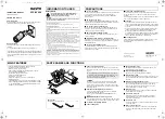
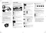
PARTS NAMES AND FUNCTIONS
INSTRUCTION MANUAL
(Warranty attached)
COLOR CCD camera
About this manual
Before installing and using the camera, please read this manual
carefully. Be sure to keep it handy for later reference.
Approvals: IP66
This camera has been certified to IP66 standard when properly
installed.
Use only an IP66 certified enclosure or an electrical box.
Safety Guard
This installation should be made by a qualified service person and should conform to
all local codes.
■
■
■
■
In case of problem
Do not use the unit if smoke or a strange odor comes from the unit,
or if it seems not to function correctly. Turn off the power
immediately, and consult your dealer or a Sanyo Authorized
Service Center.
■
■
■
■
Do not open or modify
Do not open the cabinet except during adjustment, as it may be
dangerous and cause damage to the unit. For repairs, consult your
dealer or a Sanyo Authorized Service Center.
■
■
■
■
Do not put objects inside the unit
Make sure that no metal objects or flammable substance get
inside the camera. If used with a foreign object inside, it could
cause a fire, short-circuits or damage.
■
■
■
■
Be careful when handling the unit
To prevent damages, do not drop the unit or subject it to strong
shock or vibration.
■
■
■
■
Install away from electric or magnetic fields
If installed close to a TV, radio transmitter, magnet, electric motor,
transformer, or audio speakers, the magnetic field they generate
will distort the image.
■
■
■
■
Protect from humidity and dust
To prevent damages to the unit, do not install it where there is
greasy smoke or steam, where the dampness may get too high, or
where there is a lot of dust.
■
■
■
■
Protect from high temperatures
Do not install close to stoves, or other heat generating devices,
such as spotlights, etc., or where it could be subject to direct
sunlight.
Be careful when installing close to the ceiling, in a kitchen or boiler
room, as the temperature may raise to high levels.
■
■
■
■
Cleaning
• Dirt can be removed from the cabinet by wiping it with a soft
cloth. To remove stains, wipe with a soft cloth moistened with a
soft detergent solution and wrung dry, then dry by wiping with a
soft cloth.
• Do not use benzine, thinner or other chemical product on the
cabinet, as that may cause deformation and paint peeling.
Before using a chemical cloth, make sure to read all
accompanying instructions. Make sure that no plastic or rubber
material comes in contact with the cabinet for a long period of
time, as that may cause damage or paint peeling.
■
■
■
■
Mounting Surface
The mounting surface material must be strong enough to secure
the camera. Plaster-board without a backing plate is not
recommended.
Printed on recycled paper
1AC6P1P2775--
L5AV4/US (0404KP-SY)
Depending on the conditions of use, installation and environment,
please be sure to make the appropriate settings and adjustments.
If you need help with installation and/or settings, please consult
your dealer.
INFORMATION TO USER
THIS SYMBOL INDICATES THAT THERE ARE IMPORTANT
OPERATING AND MAINTENANCE INSTRUCTIONS IN THE
LITERATURE ACCOMPANYING THIS UNIT.
WARNING:
TO PREVENT THE RISK OF FIRE OR ELECTRIC SHOCK, DO NOT EXPOSE
THIS APPLIANCE TO RAIN OR MOISTURE.
For the customers in Canada
This Class B digital apparatus complies with Canadian ICES-003.
Pour la clientèle canadienne
Cet appareil numerique de la Classe B est conforme à la norme NMB-003 du
Canada.
This equipment has been tested and found to comply with the limits for a Class B
digital device, pursuant to Part 15 of the FCC Rules.
These limits are designed to provide reasonable protection against harmful
interference in a residential installation. This equipment generates, uses, and can
radiate radio frequency energy and, if not installed and used in accordance with the
instructions, may cause harmful interference to radio communications.
However, there is no guarantee that interference will not occur in a particular
installation. If this equipment does cause harmful interference to radio or television
reception, which can be determined by turning the equipment off and on, the user is
encouraged to try to correct the interference by one or more of the following
measures:
– Reorient or relocate the receiving antenna.
– Increase the separation between the equipment and receiver.
– Connect the equipment into an outlet on a circuit different from that to which the
receiver is connected.
– Consult the dealer or an experienced radio/TV technician for help.
This device complies with Part 15 of the FCC Rules. Operation is subject to the
following two conditions: (1) This device may not cause harmful interference, and
(2) this device must accept any interference received, including interference that
may cause undesired operation.
Changes or modifications not expressly approved by Sanyo may void the user's
authority to operate this camera.
PRECAUTIONS
SANYO Electric Co., Ltd.
Printed in Japan
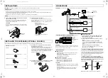
• Complies with IP66 international waterproof rating
• 1/4-inch CCD solid-state image device
• Number of pixels: 410,000 pixels
• High sensitivity, minimum required illumination of 0.04 lx
(F1.4, Gain high and B/W mode)
• Horizontal resolution of 520 TV lines
• Vari-focal lens with automatic iris
• Internal sync. / Line-Lock
• Dual power supply: AC 24 V / DC 12 V (lead wire)
• Day/Night function*
*The Day/Night function is a function that can adapt to a wide
range of changing luminance levels by automatically switching
to color during daytime, or to black-and-white at times of low
luminance such as nighttime.
1
1
1
1
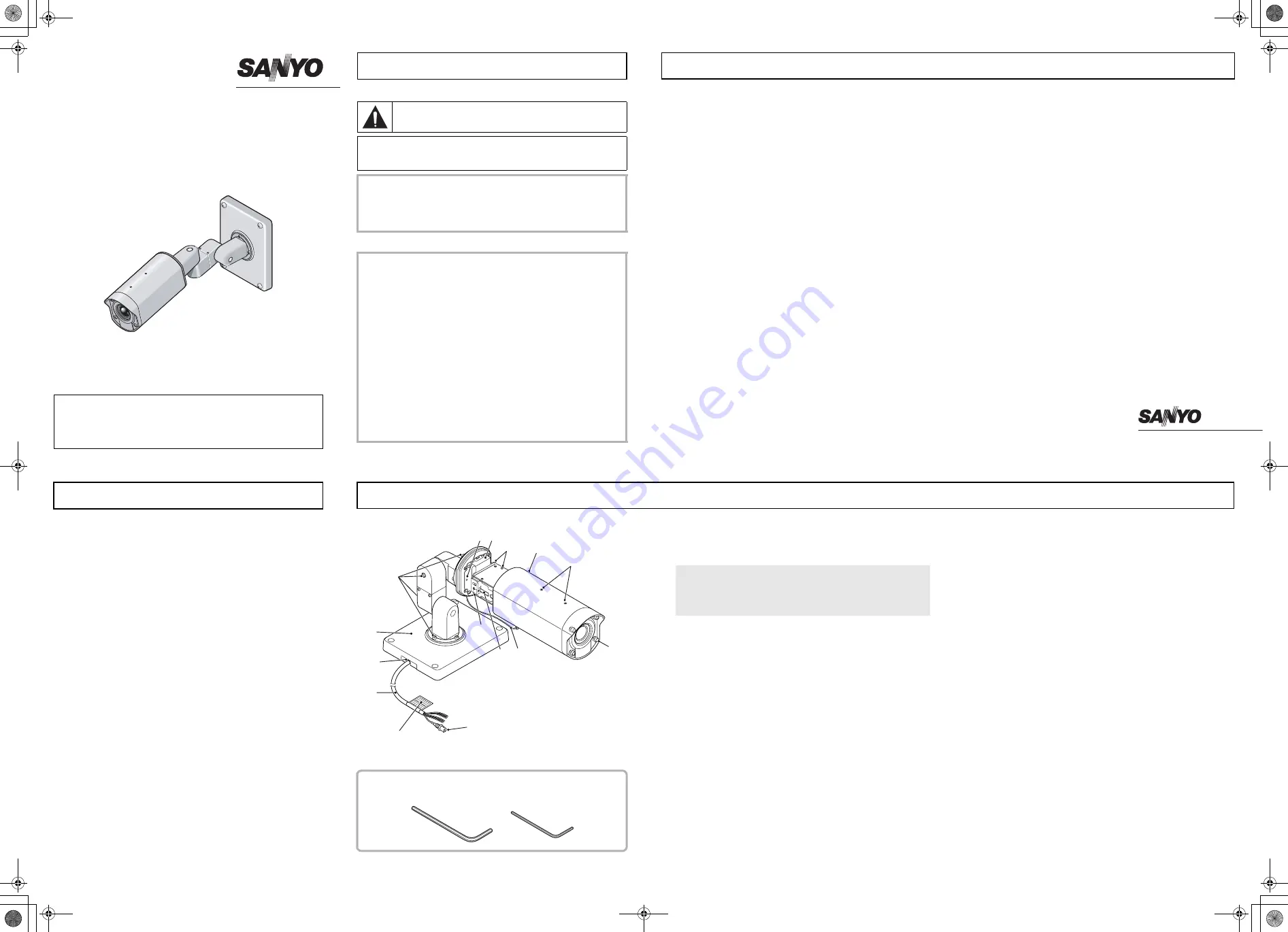
Camera cover fixing screws
There is no need to remove the camera cover except during
adjustment. If you remove the camera cover, loosen these four
screws.
CAUTION:
The camera cover will come off if the camera cover fixing
screws are loosened by about 5 mm, so be careful not to
loosen them too much. If a crew is loosened too much, the
drop-prevention washer inside the cover may come off and the
screw may fall out.
2
2
2
2
Sunshade mounting bracket screw holes
Use the sunshade mounting bracket screws to install the
sunshade (Optional; VA-SS400).
Please refer to “INSTALLING THE SUNSHADE” in this
manual.
3
3
3
3
MONITOR pin and the screw for ground
You can use this pin for video output and the screw for ground
to display an image on a monitor when setting up the camera.
4
4
4
4
L-shaped camera fixing bracket
5
5
5
5
Camera fixing base
6
6
6
6
Drop-prevention chain
Keep this attached at all times to prevent the camera cover
from falling down during installation.
7
7
7
7
Camera adjustment/setting panel
The camera can be set using switches and dials.
8
8
8
8
Camera fixing screw
You can use the hexagon wrench (small, accessory) to loosen
this screw and then remove the camera unit for replacing the
desiccant.
9
9
9
9
Camera position adjustment screws
You can use the hexagon wrench (large, accessory) to loosen
these screws and then adjust the direction of the camera.
There are four screws on the camera mount, four on the
camera itself and two on the arm section.
F
F
F
F
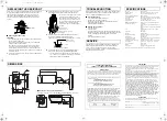
Camera mount
Used to install the camera to a wall or ceiling with mounting
screws (M8x4, sold separately).
G
G
G
G
Connection cord hole
If routing the connection cord outside the wall, install the
camera so that this hole is facing downward and pull the
connection cord out from it.
H
H
H
H
Connection cord
Connect the cables in accordance with the information on the
color display label.
I
I
I
I
Video output connector
Connection this connector to a device such as a digital video
recorder (or time-lapse VCR) or monitor with a video input
connector.
MAIN FEATURES
Accessories
Hexagon wrench (large)(small)....................................... 1 pc
6
2
3
4
5
9
F
G
H
8
7
I
1
Camera cover
Color display label
When reinstalling it, provisionally tighten the four camera
cover fixing screws and then they must be torqued to 0.5 – 1
N·m (5 – 10 kgf·cm/4.4 – 8.8 in·lbs) to ensure that the
waterproof integrity is maintained.
VCC-XV400
!"#$%#&


