3
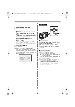
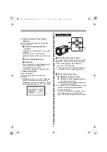
Parts Names and Functions
1
VIDEO OUT connector (BNC type)
Outputs video signal.
Connect this terminal to the video input terminal
of the external device.
2
Control terminals (Push-lock)
Used to perform the control functions such as
controlling the camera remotely or inputting/
outputting alarm.
1
ALARM IN 1/2 terminal
These terminals can be used as an input
terminal for either of the following functions.
<Alarm input terminal>
Used to connect the alarm device that
detects intruders.
Connect this terminal to an external alarm
switch or an infrared sensor, etc.
<Day/Night function terminal>
Used to switch the viewing mode manually
between the color mode and the black/white
mode.
To do so, select [DAY/NIGHT], choose
“COLOR”, and set the [EXT ALARM] to the
desired alarm input channel.
2
ALARM OUT terminal
Used to connect to an external buzzer or
lamp.
When an alarm is detected, the device
connected to the terminal notifies that an
alarm is detected.
3
COM terminal (earth terminal)
4
FOCUS terminal
Used to perform the focus adjustment
remotely by connecting an external switch.
• DC ± (6 - 12 V), +: FAR, –: NEAR
5
ZOOM terminal
Used to zoom in/out by connecting an
external switch.
• DC ± (6 - 12 V), +: WIDE, –: TELE
Rear panel
RS485
A
B
POWER
VIDEO OUT
ALARM IN 2
ALARM IN 1
ALARM OUT
COM
FOCUS
ZOOM
UTP
COM
AC24V
DC12V
GND
ALARM IN 2
ALARM IN 1
ALARM OUT
COM
FOCUS
ZOOM
1
4
2
4
3
5
1
RS485
A
B
UTP
COM
3
2
3
2
1
POWER lamp
b
How to use the push-lock switch
When connecting the cable, press and hold
down the protrusion of the terminal, insert the
cable into the terminal, and then release the
protrusion.
L5CB2_XE(INSTALLATION).book 3 ページ 2008年1月23日 水曜日 午後1時38分

