11
PREP
ARA
TION
CONTROL NAMES AND LOCATIONS (Cont’d)
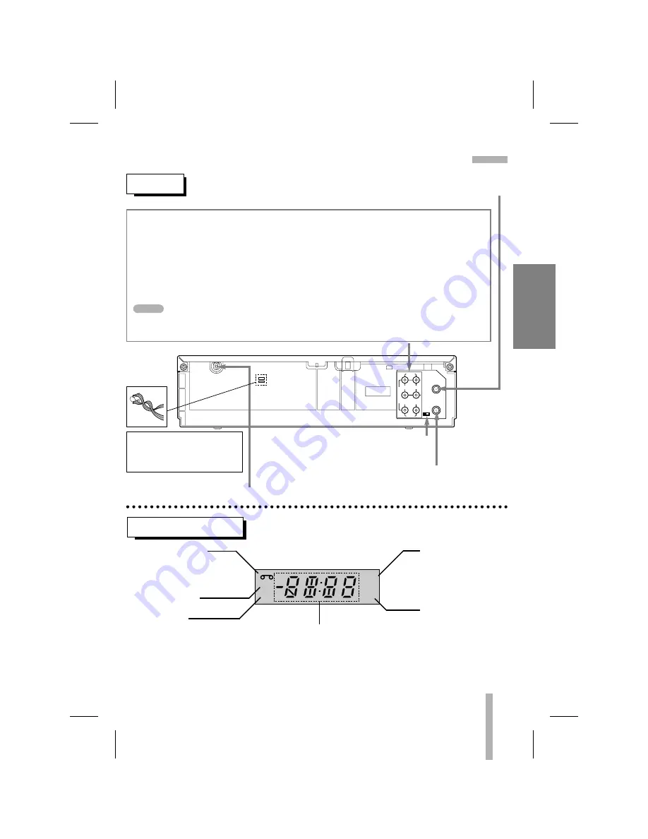
INDICATOR PANEL
Cassette indicator
Lights while a cassette is
inserted, and flashes while
ejecting a cassette.
Record indicator
VCR indicator
Use TV/VCR on the remote control
to turn this indicator ON or OFF.
ON: for playback, VCR programming
or watching TV programs through the
VCR tuner
OFF: for watching TV programs
through TV tuner
REC
VCR
TIMER
AM
Clock/Tape operation indicator
HI — VCR is turned on.
BYE — VCR is turned off.
TIMER indicator
AM indicator
(PM is not displayed)
AUDIO
LINE1(AUX1)
R
L
IN
IN
OUT
OUT
ANT.IN
VIDEO
CH.
3
4
VHF/UHF
/CATV
REAR
ANTENNA INPUT CONNECTOR
Connect the VHF/UHF/CATV antenna to this terminal.
AUDIO OUT (L/R) JACKS; Connect this terminal to the audio input terminal on an exter-
nal unit (Audio System, TV/Monitor, Another VCR).
VIDEO OUT JACK; Connect this terminal to the video input terminal on an external unit
(TV/Monitor, Another VCR).
AUDIO IN (L/R) JACKS; Connect the audio output cable from an external unit (ex. Audio
system, TV/Monitor, DVD player, Another VCR) to this terminal.
VIDEO IN JACK; Connect the video output cable from an external unit (ex. Audio system,
TV/Monitor, DVD player, Another VCR) to this terminal.
When using this AUDIO/VIDEO IN jacks, select the input channel “LINE1” at the VCR.
Press INPUT to select “LINE1”.
NOTE
POWER CORD
Connect only to an AC 120V, 60Hz outlet.
VCR OUTPUT CHANNEL SELECT SWITCH
Set this switch to channel 3 or 4.
VHF/UHF/CATV ANTENNA OUTPUT CONNECTOR
Connect this terminal to the VHF or UHF
antenna terminals on the back of a TV.
WARNING : Do not drop the tying
band of the power cord into the
unit. Doing so might cause a fire
or an electrical shock.


