2-1
SECTION2 CABINET & MAIN FRAME
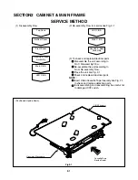
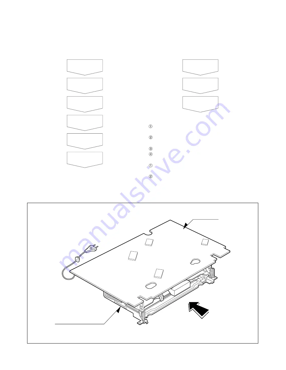
Fig.2-1
SERVICE METHOD
(1) Disassembly Flow
(Positioned Upside Down)
(2) Re-assembly Flow for service like Fig. 2-1
(3) To check and replace Electrical parts
1
Disassemble the unit according to
No.1) Disassembly Flow.
2
Re-assemble the unit according to
No.2) Re-assembly Flow.
3
Place the unit like Fig. 2-1
4
Check and replace Electrical parts.
NOTE :
1
Insert Video Cassette Tape inversely like Fig. 2-1
to check and replace defective parts.
2
In disassembling and reassembling, be careful not
to damaged CST switch.
Top Case
Bottom Cover
Front Panel
Housing & Deck
Assembly
Main C.B.A
LED C.B.A
LED C.B.A
Main C.B.A
Housing & Deck
Assembly
Housing y Mecanismo
Cassette Tape
(Upside Down)
C.B.A Princioal
Summary of Contents for VHR-VK310A
Page 65: ...MEMO ...
Page 118: ......


