background image

– 4 –

Fig. 2

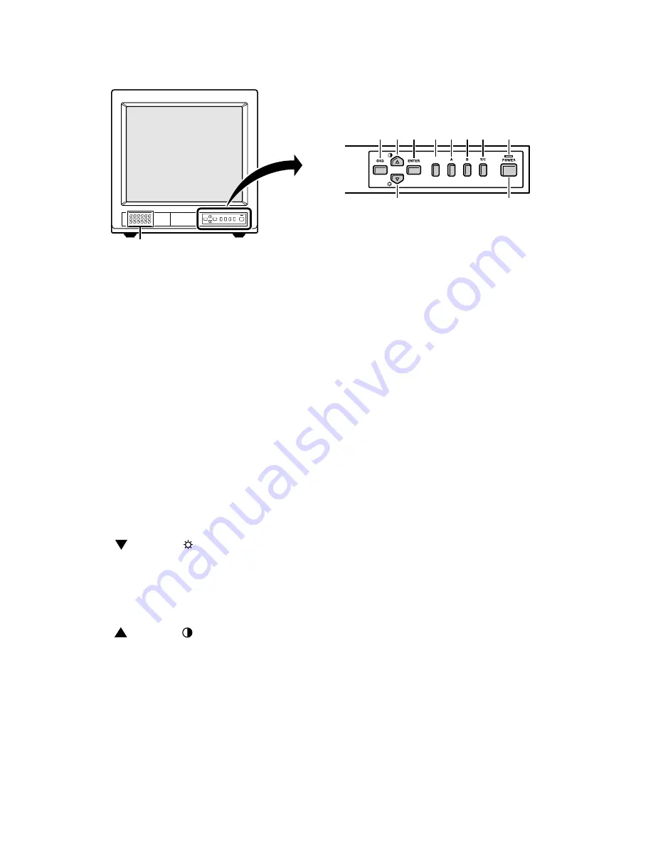
1.  Speaker

When the monitor selector button (A, B or Y/C)

is pressed, the speaker lets you hear the sound

from the components which are connected to

the terminals at the rear of the monitor. (Use

components which produce audio output.)

2.  On-screen display button (OSD)

When this button is pressed, the menu screen

appears on the monitor screen.

3.  Cursor (    )  button (    )

When this  button is pressed, the cursor moves

down. When it reaches the bottom, it reappears

at the top. In addition, this button is used to

make adjustment values smaller.

4.  Cursor (    )  button (    )

When this  button is pressed, the cursor moves

up. When it reaches the top, it reappears at the

bottom. In addition, this button is used to make

adjustment values larger.

5.  Display selector button (ENTER)

If this  button is pressed while a picture is on the

monitor screen, the screen changes to the

adjustment screen. If the button is pressed once

more, the picture returns to the previous screen.

1. OPERATING INSTRUCTIONS

1-1. FRONT PANEL CONTROLS

2

4

5

6

7

G

3

F

1

SCAN

9

8

1.COLOR

2.TINT

3.BRIGHTNESS

4.CONTRAST

5.SHARPNESS

6.VOLUME

8.LANGUAGE

9.TITLE

10.VERSION


6.  Underscan/overscan select button (SCAN)

The initial setting is for the normal screen

(overscan). If the SCAN button is pressed, the

screen will become smaller (underscan) than

the normal screen. Change this setting in cases

such as when screen display characters are

missing. If the CSAN button is pressed once

more, the normal screen is display again.

7.  Monitor A selector button (A)

When this  button is pressed, the audio and

video input changes to the component which is

connected to the A terminals at the rear of the

monitor.

8.  Monitor B serector button (B)

When this  button is pressed, the audio and

video input changes to the component which is

connected to the B terminals at the rear of the

monitor.

9.  Monitor Y/C selector button (Y/C)

When this  button is pressed, the audio and

video input changes to the component which is

connected to the Y/C terminals at the rear of the

monitor.

10.  Power indicator (POWER)

Lights when the power is on.

11.  Power button (POWER)

Press this button to turn the power on and off.

Summary of Contents for VMC-8618

Page 1: ... 3 N S P Not available as service parts Design and specifications are subject to change without notice Product Code 114 950 71 U S A Canada SERVICE MANUAL Color Video Monitor CONTENTS SPECIFICATIONS 3 1 OPERATING INSTRUCTIONS 4 2 SERVICE ADJUSTMENTS 6 3 PARTS LIST 10 CIRCUIT DIAGRAMS Product Code 114 950 74 Europe VMC 8619P Product Code 114 950 76 U K Product Code 114 950 78 Australia ...

Page 2: ...gs 3 Before returning the set to the customer always perform an AC leakage current check on the exposed metallic parts of the cabinet such as terminals screwheads metal over lays etc to be sure that the set is safe to operate without the danger of electrical shock Plug the AC line cord directly into a 120 V AC outlet Do not use a line isolation trans former during this check Use an AC voltmeter wi...

Page 3: ... ohm negative sync C signal 0 286 Vp p 75 ohm negative sync bridge connection possible Composite sync signal 1 0 Vp p 75 ohm BNC connector 2 automatic temination setting Audio signal 6dBs 400 mVrms RCA pin 3 bridge connection possible YES 1 W Variable round x 1 100 to 240 V AC 50 60 Hz 95 Watts 10 C to 45 C storage temperature 10 to 90 448 x 443 x 447 mm 25kg SPECIFICATIONS Color system Picture tu...

Page 4: ...RUCTIONS 1 1 FRONT PANEL CONTROLS 2 4 5 6 7 G 3 F 1 SCAN 9 8 1 COLOR 2 TINT 3 BRIGHTNESS 4 CONTRAST 5 SHARPNESS 6 VOLUME 8 LANGUAGE 9 TITLE 10 VERSION 6 Underscan overscan select button SCAN The initial setting is for the normal screen overscan If the SCAN button is pressed the screen will become smaller underscan than the normal screen Change this setting in cases such as when screen display char...

Page 5: ...onitored 3 Rear B terminals AUDIO VIDEO B terminals When the monitor B selector button at the front of the monitor is pressed the audio and video signals from the component which is connected to these terminals can be monitored 4 Rear Y C terminals AUDIO VIDEO Y C terminals When the monitor Y C selector button at the front of the monitor is pressed the audio and video signals from the component wh...

Page 6: ...ke right and left of picture to 1 Adjusting VR306 make signal side of picture of scale at 1 5 0 5 position Adjusting vertical linear control VR302 for equal spacing of lines between center extreme of scan Max Min Aver age 10 Adjusting vertical center control VR303 to 1 Adjusting vertical size control VR301 make signal side of scale is 1 0 3 position VR503 FTB FOCUS VR1 and VR2 VR401 VR306 VR302 VR...

Page 7: ...805 FBT FOCUS VR VR804 VR802 VR501 VR801 VR803 VR805 FBT FOCUS VR VR804 VR802 VR501 FBT SCREEN VR VR501 VR502 VR305 Adjust VR805 G Bias to center Adjust FBT screen VR make luminance without video to 1 0 1 5 FL Adjust VR801 make X value is 0 281 0 015 Adjust VR803 make Y value is 0 298 0 015 Adjust VR501 make luminance with video signal to 38 42 FL Adjust VR804 make X value is 0 281 0 015 Adjust VR...

Page 8: ...VR TO MAX BRIGHT VR CONTRAST VR and SHARPNESS VR TO MAX VR801 VR802 VR803 VR804 VR805 FBT SCREEN VR VR804 VR802 VR501 VR801 VR802 VR803 VR804 and VR805 is center position Adjust the VR801 VR803 and FBT SCREEN VR to dark gray with screen Adjust the VR802 and VR804 to white gray with screen Adjust the VR501 it makes the screen of the monitor proper brightness The way of adjusting it which a color an...

Page 9: ...VR302 T902 PIN VR306 VR804 VR805 VR801 VR802 VR803 Q804 Q802 Q806 S108 S107 LED101 S106 S104 S101 S103 S102 S105 ABL H SIZE H PHASE X RAY V CENTER VR304 V SIZE V LIN R GAIN R BAIS B BAIS G BAIS B GAIN Fig 4 Fig 5 Fig 6 MAIN BOARD Foil side FUNCTION BOARD Foil side VIDEO BOARD Foil side ...

Page 10: ...4928 RUBBER WASHERDIA20 DIA6 1T 19 645 046 4966 WASHER 6 5 19 1MM 20 645 046 4843 PH SCREW 6 12MM 21 645 040 9226 X RADIATION 110 50MM 22 645 046 6076 DEGAUSSING COIL CH 19DXA 23 645 046 6656 VIDEO BOARD CH 19DXA 24 645 046 6359 METAL CABINET CH 19DXA AA 51 25 645 034 3919 HANDLE COVER CM 14 PA 765A 26 645 034 3582 PH W W SCR 4 8MM 27 645 034 3841 ID LABEL 83 51MM N S P 28 645 034 3612 SCREW WASHE...

Page 11: ...AL 200OHM 6DIA VR803 645 034 3469 POT VR METAL 10 KOHM 6DIA VR804 645 048 3370 POT VR METAL 200OHM 6DIA VR805 645 046 4805 POT VR METAL 5 KOHM 6DIA MISCELLANEOUS SK801 645 046 5246 CRT SOCKET CRT 8PIN 29DIA W801 645 034 3773 CONNECTOR BASE M241855 N S P W802 645 034 3759 CONNECTOR BASE M241854 X N S P G2 645 034 3667 CONNECTOR BASE P235142 N S P GND1 645 034 3698 CONNECTOR BASE M11352 N S P MAIN B...

Page 12: ... 645 046 4287 MEMB CAP 1UF 63V 5 C928 645 034 2608 EC CAP 100UF 16 V C929 645 034 2837 CC CAP 104PF 50V Y5V C930 645 034 2653 EC CAP 1000UF 16V 10DIA C931 645 045 9979 EC CAP 470UF 25 V C932 645 034 2837 CC CAP 104PF 50V Y5V C933 645 046 3600 EC CAP 1000UF 10V 105DEG C936 645 046 3679 EC CAP 22UF 250V 105DEG DIODES D101 645 034 3308 DIODE 1N4148 D102 645 034 3308 DIODE 1N4148 D103 645 034 3308 DIO...

Page 13: ...6 2191 CF RES 10 KOHM 1 6W 5 R156 645 046 2474 CF RES 2 2 KOHM 1 6W 5 R157 645 046 2634 CF RES 33 KOHM 1 6W 5 R158 645 046 2795 CF RES 47 KOHM 1 6W 5 R159 645 034 1854 CF RES 1 KOHM 1 6W 5 R160 645 046 2191 CF RES 10 KOHM 1 6W 5 R161 645 046 2696 CF RES 3 9 KOHM 1 6W 5 R162 645 046 2849 CF RES 5 1 KOHM 1 6W 5 R163 645 046 2740 CF RES 43 KOHM 1 6W 5 R165 645 046 2191 CF RES 10 KOHM 1 6W 5 R166 645 ...

Page 14: ...S 10S T502 645 046 6014 FBT TRANS CH 19DXA T503 645 046 6021 FOCUS TRANS CH 19DXA T901 645 048 3615 LINE FILTER CH 19DXA 30MH T902 645 048 3592 POWER TRANS CH 19DXA VDE VARIABLE RESISTORS VR301 645 046 4720 POT VR METAL 100OHM 6DIA VR302 645 034 3476 POT VR METAL 10 KOHM 6DIA VR303 645 034 3476 POT VR METAL 10 KOHM 6DIA VR305 645 034 3476 POT VR METAL 10 KOHM 6DIA VR306 645 034 3476 POT VR METAL 1...

Page 15: ...45 046 2467 CF RES 220OHM 1 6W 5 R224 645 046 2467 CF RES 220OHM 1 6W 5 R225 645 046 3006 CF RES 680 KOHM 1 6W 5 R226 645 046 2474 CF RES 2 2 KOHM 1 6W 5 R227 645 034 1854 CF RES 1 KOHM 1 6W 5 R228 645 034 1854 CF RES 1 KOHM 1 6W 5 R229 645 046 2467 CF RES 220OHM 1 6W 5 R256 645 046 2757 CF RES 47OHM 1 6W 5 R257 645 046 2757 CF RES 47OHM 1 6W 5 R258 645 034 1854 CF RES 1 KOHM 1 6W 5 R259 645 034 1...

Page 16: ...S P W B MAIN P W B C6 CONTROL KEY P W B C6 VIDEO P W B C7 SIGNAL P W B C7 PRODUCT SAFETY NOTICE THE COMPONENTS DESIGNATED BY A SYMBOL IN THIS SCHEMATIC DIAGRAM DESIGNATES COMPONENTS WHOSE VALUE ARE OF SPECIAL SIGNIFICANCE TO PRODUCT SAFETY SHOULD ANY COMPONENT DESIGNATED BY A SYMBOL NEED TO BE REPLACED USE ONLY THE PART DESIGNATED IN THE PARTS LIST DO NOT DEVIATE FROM THE RESISTANCE WATTAGE AND VO...

Page 17: ...18 19 A B C D E F G H I J K C1 BLOCK DIAGRAM AND CIRCUIT DIAGRAMS B901 AC IN B903 DEGAUSSING COIL B101 P101 P102 CONTROL KEY BOARD SIGNAL BOARD P201 P201 VIDEO BOARD CRT B201 W801 B904 W802 B401 H DY V DY SPEAKER B701 L8MV5 WD MAIN BOARD OVERALL WIRING BLOCK DIAGRAM ...

Page 18: ...5 6 7 8 9 10 11 12 13 14 15 16 17 18 19 A B C D E F G H I J K C2 CRITICAL SAFETY PARTS AC IN SWITCHING OSC REG REG PAL NTSC DECOCER V DEF DELAY ON SCREEN DISPLAY CONTROL C P U F F ROM AUDIO AMP F B T MAIN BOARD AND CONTROL KEY BOARD ...

Page 19: ...C D E F G H I J K 1 2 3 4 5 6 7 8 9 10 11 12 13 14 15 16 17 18 19 A B C D E F G H I J K C3 AC IN SWITCHING OSC REG REG ON SCREEN DISPLAY CONTROL C P U F F ROM AUDIO AMP MAIN BOARD AND CONTROL KEY BOARD LEFT ...

Page 20: ...A B C D E F G H I J K 1 2 3 4 5 6 7 8 9 10 11 12 13 14 15 16 17 18 19 A B C D E F G H I J K C4 CRITICAL SAFETY PARTS PAL NTSC DECOCER V DEF DELAY F B T MAIN BOARD AND CONTROL KEY BOARD RIGHT ...

Page 21: ...A B C D E F G H I J K 1 2 3 4 5 6 7 8 9 10 11 12 13 14 15 16 17 18 19 A B C D E F G H I J K C5 SIGNAL BOARD VIDEO BOARD CLM CRITICAL SAFETY PARTS SELECT SW SELECT SW SELECT SW S B A ...

Page 22: ...A B C D E F G H I J K 1 2 3 4 5 6 7 8 9 10 11 12 13 14 15 16 17 18 19 A B C D E F G H I J K C6 MAIN P W B PRINTED WIRING BOARDS P W B CONTROL KEY P W B ...

Page 23: ...A B C D E F G H I J K 1 2 3 4 5 6 7 8 9 10 11 12 13 14 15 16 17 18 19 A B C D E F G H I J K C7 SIGNAL P W B VIDEO P W B ...

Page 24: ...Nov 01 SANYO Electric Co Ltd Osaka Japan ...

Reviews: