background image

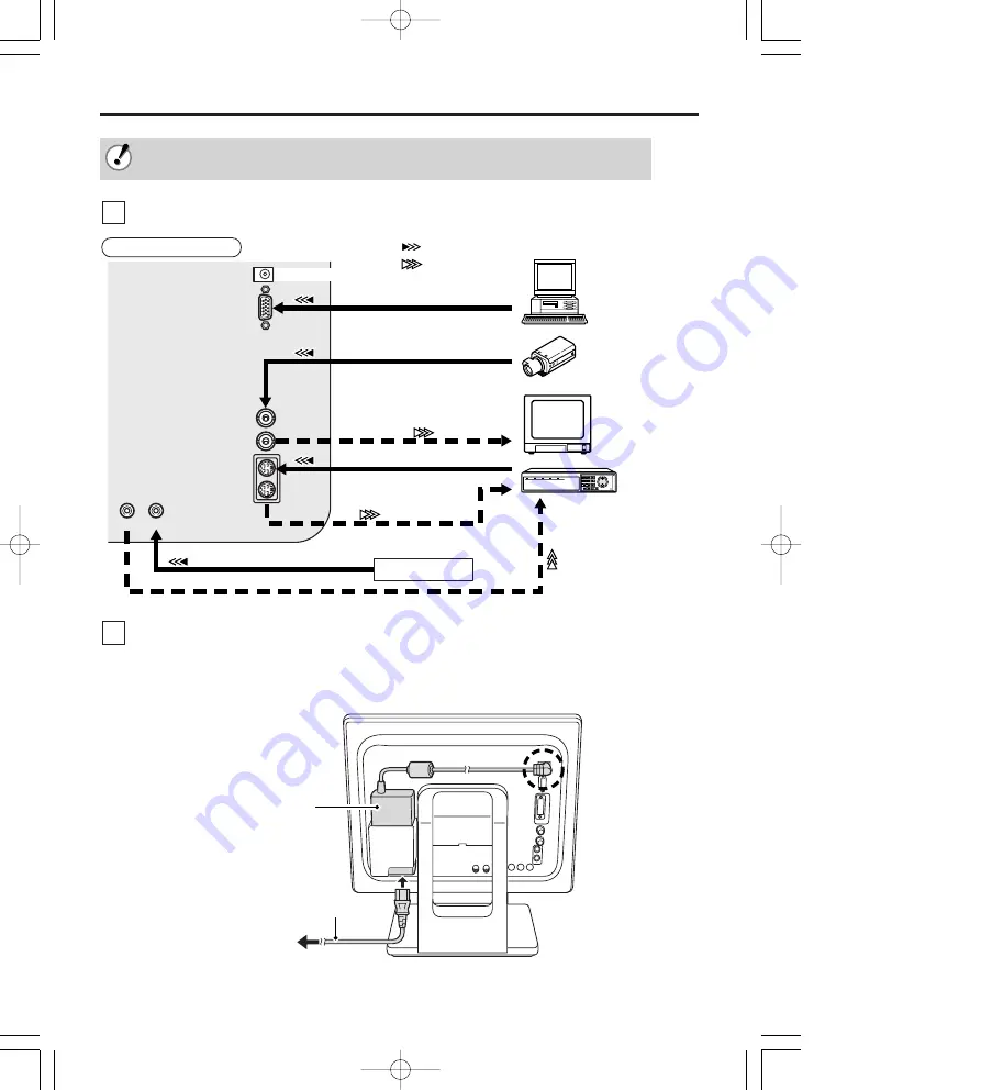
Instrucciones para la conexión

4

Español

Al conectarse, compruebe que el suministro de energía de cada unidad esté desconectado.

Los otros dispositivos y cables de conexión necesarios se venden por separado.

BNC IN

DC IN

VGA IN

BNC OUT

Y/C IN

Y/C OUT

AUDIO OUT AUDIO IN

Monitor del TV, etc.

Grabadora de disco duro, etc.

AUDIO LINE IN

VGA OUT

BNC OUT

Y/C (S-VIDEO) OUT

Y/C (S-VIDEO) IN

AUDIO LINE OUT

BNC IN

Cámara CCD, etc.

(Incluye el cable de conexión VGA)

Computadora

: Señal de entrada

: Señal de salida

Amplificador, etc.

Ejemplo de conexión

(Consulte los pasos en 

x

.)

Conecte los dispositivos a los terminales de conexión del panel posterior.

1

Adaptador de CA 
(incluido)

Cable de CA (incluido)

Conecte el cable eléctrico (DC de 12V)

2

Conecte el adaptador de CA que se incluye al terminal de entrada de energía (DC IN) y luego
conecte el cable de CA entre el adaptador y el tomacorriente de CA.
• Al conectar el cable eléctrico, el suministro de energía llegará a la unidad principal.

00̲VMC̲L1015̲17̲19̲E    06.7.19  0:01  PM    ページ 4

Summary of Contents for VMC-L1015

Page 1: ...ecifications 10 Troubleshooting 11 Features Multilingual menu support English Chinese French German Spanish Italian Japanese Picture in Picture PIP function NTSC PAL automatic select VESA Display Power Management Signaling About this manual This manual gives basic connections and operations instructions for 3 NTSC models VMC L1015 L1017 and L1019 and 3 PAL models VMC L1015P L1017P and L1019P For m...

Page 2: ...e instructions may cause harmful interference to radio communications However there is no guarantee that interference will not occur in a particular installation If this equipment does cause harmful interference radio or television reception which can be determined by turning the equipment off and on the user is encouraged to try to correct the interference by one or more of the following measures...

Page 3: ...is unit under the following conditions in extremely hot cold or humid places in dusty places near appliances generating strong magnetic fields in places subject to direct sunlight in badly ventilated places in automobiles with doors closed Do not cover the ventilation slots while in operation as this could obstruct the required ventilation flow When dust accumulates on the screen surface clean it ...

Page 4: ...l MODE Changes the input mode Page 6 Power button POWER Turns the power on or off w e q r t y Power indicator light When no signals are being input to any of the following input terminals the monitor switches automatically to power saving mode The screen will switch to a blue screen Power Saving will appear after approximately 10 seconds and then it will switch to a black screen To cancel power sa...

Page 5: ...io Out terminal AUDIO OUT For audio output Power input terminal DC IN Page 5 Composite signal input terminal BNC IN For the input of CCD camera surveillance image signal Composite signal output terminal BNC OUT Sends the image to BNC IN VGA signal input terminal Signal Red signal Green signal Blue signal No use No use GND Red GND Green GND Blue No use GND sync No use SDA H sync V sync SCL q w e r ...

Page 6: ...INE OUT BNC IN CCD Camera etc Included VGAconnecting cable Computer Input signal Output signal Amplifier etc Connection example Refer to x for steps Connect the devices to the connection terminals at the rear panel 1 AC adapter included AC cord Included Connect the power cord DC 12V 2 Connect the included AC adapter plug to the power input terminal DC IN and then connect the AC cord between the AC...

Page 7: ... the chosen signal 2 3 seconds later When there is no input detected on the chosen signal No signal will be displayed If the power to the connected device is off Video Loss will be displayed Adjust the brightness 0 51 As the brightness is being adjusted the symbol will be displayed in the upper left of the screen Adjust the contrast 0 51 As the contrast is being adjusted the symbol will be display...

Page 8: ...ntrast Adjust the contrast 0 51 25 Sharpness Adjust the sharpness 0 51 4 Volume Adjust the volume 0 51 10 H Position Adjust the horizontal position of the display 0 51 25 English 中文 日本語 Language Select the language of the display Français Español English Deutsch Italiano Color Temp Select the color temperature 9300 K 6500 K Standard Standard Scan Select the image scan type Over Under Full 1 1 Full...

Page 9: ...n the screen is flickering etc 0 51 8 Color Temp Select the color temperature 9300 K 6500 K User color User color User Color R Adjust the Red when Color temp is set to User color 0 51 51 User Color G Adjust the Green when Color temp is set to User color 0 51 51 User Color B Adjust the Blue when Color temp is set to User color 0 51 51 OSD H Pos Adjust the horizontal position of the adjustment panel...

Page 10: ... the or button to change the size of the sub window to one of three sizes Press the adjustment control MENU Press the or button to select PIP SIZE POS and then press the or button to select Pip Pos Use the following buttons to determine the display position and buttons Move the sub window to the right and left and buttons Move the sub window up and down 7 6 5 4 The sound and luminance cannot be ad...

Page 11: ...4 x 768 250 cd m2 5 11 ms 1280 x 1024 300 cd m2 Composite sync signal 1 0 Vp p 75 Ω BNC connector Separate Y C signal mini DIN connector Y signal 1 0 Vp p 75 Ω negative sync C signal 0 286 Vp p 75 Ω negative sync 6 dBs 400 mVrms RCA pin English Chinese French German Spanish Italian Japanese Approx 1 W DC 12 V 4 16 A Temperature 0 C 40 C Humidity 20 85 non condensation Temperature 20 C 60 C Humidit...

Page 12: ... displayed Is the connected device outputting a video signal Is the connection correct Page 5 Using the input mode control MODE is the correct input signal selected Page 6 No sound is heard Is the connected device outputting an audio signal Is the connection correct Page 5 Check the volume level is not set to 0 Page 6 8 The display is dark Are the brightness and contrast set to the correct level P...

Page 13: ...nisch Japanisch Bild in Bild Funktion PIP Automatische NTSC PAL Umschaltung VESA Display Power Management Signaling Über diese Anleitung In dieser Anleitung werden die Grundanschlüsse und Bedienungsanweisungen für die drei NTSC Modelle VMC L1015 L1017 und L1019 und die drei PAL Modelle VMC L1015P L1017P and L1019P beschrieben Für nähere Informationen über die Modellvarianten wird auf die technisch...

Page 14: ...gen an einen qualifizierten Fachmann bei beschädigtem oder ausgefranstem Netzkabel falls Flüssigkeiten in das Gerät eingedrungen sind falls das Gerät fallen gelassen wurde oder das Gehäuse beschädigt ist falls deutliche Leistungsänderungen auftreten Versuchen Sie niemals das Gerät selbst zu warten weil Sie sich beim Öffnen von Abdeckungen gefährlichen Spannungen und anderen Gefahren aussetzen könn...

Page 15: ...er Betriebsart Seite 5 Netztaste POWER Zum Ein und Ausschalten der Stromversorgung w e q r t y Netzanzeige Falls an den folgenden Eingangsbuchsen kein Signal anliegt wird der Monitor automatisch in die Energiesparbetriebsart umgeschaltet Es wird auf einen blauen Bildschirm umgeschaltet die Anzeige Power Saving erscheint für ungefähr 10 Sekunden und danach wird auf einen schwarzen Bildschirm umgesc...

Page 16: ...usgang Gleichstrombuchse DC IN Seite 4 Eingangsbuchse für Composite Signal BNC IN Für den Eingang eines Signals von einer CCD Überwachungskamera Ausgangsbuchse für Composite Signal BNC OUT Übertragung der Bildsignale von der Buchse BNC IN VGA Eingangsbuchse Signal Rotsignal Grünsignal Blausignal Nicht verwendet Nicht verwendet Masse rot Masse grün Masse blau Nicht verwendet Masse Synchro Nicht ver...

Page 17: ...a usw mitgeliefertes VGA Anschlusskabel Computer Eingangssignal Ausgangssignal Verstärker usw Anschlussbeispiel Für die Anweisung wird auf x verwiesen Schließen Sie die Geräte an den rückseitigen Buchsen an 1 Netzgerät mitgeliefert Netzkabel mitgeliefert Schließen Sie das Gleichstromkabel DC 12V an 2 Schließen Sie den Netzgerätestecker an der Gleichstrombuchse DC IN an und verbinden Sie das Netzge...

Page 18: ... angezeigt Falls am eingestellten Signaleingang kein Signal anliegt erscheint die Anzeige No signal Falls das angeschlossenen Gerät ausgeschaltet ist erscheint die Anzeige Video Loss Stellen Sie die Helligkeit ein 0 51 Während der Einstellung der Helligkeit wird in der oberen linken Bildschirmecke das Symbol eingeblendet Stellen Sie den Kontrast ein 0 51 Während der Einstellung des Kontrasts wird ...

Page 19: ...0 51 4 Volumen Einstellung des Lautstärkepegels 0 51 10 H Position Einstellung der horizontalen Position der Anzeige 0 51 25 English 中文 日本語 Sprache Einstellung der Anzeigesprache Français Español English Deutsch Italiano Farb Temp Einstellung der Farbtemperatur 9300 K 6500 K Standard Standard Scannen Einstellung der Bildabtastung Über Unter Voll 1 1 Voll PIP Einstellung der Bild in Bild Funktion E...

Page 20: ...instel Farbe Einstellung Einstellung von Rot falls die Farbtemperatur auf einen Rot Benutzerwert eingestellt ist 0 51 51 Einstellung Einstellung von Grün falls die Farbtemperatur auf einen Grün Benutzerwert eingestellt ist 0 51 51 Einstellung Einstellung von Blau falls die Farbtemperatur auf einen Blau Benutzerwert eingestellt ist 0 51 51 OSD H POS Einstellung der horizontalen Position des Anzeige...

Page 21: ...t Schärfe Volumen H Position Sprache Farb Temp Scannen PIP PIP SIZE POS Display Mode Zurücksetzen 1 Stellen Sie mit den Tasten oder die Größe des Unterfensters drei verschiedene Größen ein Drücken Sie die Einstelltaste MENU Stellen Sie mit den Tasten oder PIP SIZE POS ein und stellen Sie danach mit den Tasten oder Pip Pos ein Bestimmen Sie die Anzeigeposition mit den folgenden vier Tasten Tasten u...

Page 22: ... Seite 5 Keine Tonwiedergabe Liegt vom angeschlossenen Gerät ein Audiosignal an Ist der Anschluss richtig ausgeführt Seite 4 Kontrollieren ob der Lautstärkepegel nicht auf 0 eingestellt ist Seiten 5 7 Dunkler Bildschirm Sind die Helligkeit und der Kontrast richtig eingestellt Seiten 5 7 Flimmernder Bildschirm Befindet sich in der Nähe ein Gerät das starke Magnetfelder erzeugt Falls ja das Gerät en...

Page 23: ...trix TFT LCD Bildschirm 381 mm diagonal 304 x 228 mm 4 3 0 297 x 0 297 mm 1024 x 768 250 cd m2 5 11 ms 1280 x 1024 300 cd m2 Composite sync Signal 1 0 Vp p 75 Ω BNC Stecker Separate Y C Signale Mini DIN Anschluss Y Signal 1 0 Vp p 75 Ω negative synchronisation C Signal 0 286 Vp p 75 Ω negative synchronisation 6 dBs 400 mVrms RCA Klemme Englisch Chinesisch Französisch Deutsch Spanisch Italienisch J...

Page 24: ...en wird 5 40 A B G H C D F E Ansicht von der Rückseite Ansicht Frontseite Ansicht von der Seite Modell VMC L1015 L1015P VMC L1017 L1017P VMC L1019 L1019P A 353 2 375 421 2 B 305 2 341 379 4 C 229 1 273 4 304 D 286 318 353 6 E 338 370 405 6 F 52 G 36 4 41 6 44 6 H 170 Abmessungen System NTSC PAL Modell Links rechts 70 70 75 75 75 75 70 70 75 75 75 75 Auf ab 60 65 70 60 70 60 60 65 70 60 70 60 Blick...

Page 25: ...ois Français Allemand Espagnol Italien Japonais Fonction Image dans l Image PIP Sélection automatique NTSC PAL Signalisation de gestion du courant à affichage VESA À propos de ce manuel Ce manuel donne les instructions concernant les connexions de base et l utilisation pour 3 modèles NTSC VMC L1015 L1017 et L1019 et 3 modèles PAL VMC L1015P L1017P et L1019P Pour plus de détails concernant les vari...

Page 26: ...ute ou que son coffret a été endommagé lorsque le fonctionnement de l appareil présente des signes distincts de changement Ne pas tenter d effectuer soi même des travaux d entretien ou de réparation car si les couvercles sont ouverts ou retirés il y aura risque d électrocution ou d autres accidents Toujours confier les travaux d entretien à un technicien qualifié Svp note Votre produit Sanyo est c...

Page 27: ...age 5 Commande du mode d entrée MODE Change le mode d entrée page 5 Touche d alimentation POWER Allume et éteint l appareil w e q r t y Témoin d alimentation Lorsqu aucun signal ne parvient à aucune des bornes d entrée suivantes le moniteur passe automatiquement en mode d économie d énergie L écran devient bleu Power Saving s affiche environ 10 secondes plus tard puis l écran devient noir Pour ann...

Page 28: ...O OUT Pour la sortie audio Borne d entrée d alimentation DC IN page 4 Borne d entrée de signal composite BNC IN Pour l entrée d un signal de surveillance de caméra CCD Borne de sortie de signal composite BNC OUT Envoie l image à BNC IN Borne d entrée de signal VGA Signal Signal rouge Signal vert Signal bleu Non utilisée Non utilisée MASSE rouge MASSE vert MASSE bleu Non utilisée MASSE sync Non uti...

Page 29: ...ble de connexion VGA fourni Ordinateur Signal d entrée Signal de sortie Amplificateur etc Exemple de branchement Pour les étapes reportez vous à x Branchez les appareils aux bornes de connexion sur le panneau arrière 1 Adaptateur secteur fourni Cordon secteur fourni Branchez le cordon d alimentation 12 V CC 2 Branchez la fiche de l adaptateur secteur fourni à la borne d entrée d alimentation DC IN...

Page 30: ...bleu apparaît tout d abord puis l affichage du signal choisi apparaît 2 à 3 secondes plus tard Lorsqu aucune entrée n est détecté pour le signal choisi No signal s affiche Si l appareil connecté est éteint Video Loss s affiche Réglez la luminosité 0 51 Lorsque vous réglez la luminosité le symbole s affiche dans le coin supérieur gauche de l écran Réglez le contraste 0 51 Lorsque vous réglez le con...

Page 31: ...0 51 25 Netteté Réglez la netteté 0 51 4 Volume Réglez le volume 0 51 10 Position H Réglez la position horizontale de l affichage 0 51 25 English 中文 日本語 Langues Sélectionnez la langue de l affichage Français Español English Deutsch Italiano Temp de Sélectionnez la température de couleur 9300 K 6500 K Standard couleur Standard Balayage Sélectionnez le type de balayage d image Sur Sous Plein 1 1 Ple...

Page 32: ...électionnez la température de couleur 9300 K 6500 K Régl Couleur couleur Régl Couleur Réglage Rouge Réglez le Rouge lorsque Temp de couleur est réglé sur Réglage couleur 0 51 51 Réglage Vert Réglez le Vert lorsque Temp de couleur est réglé sur Réglage couleur 0 51 51 Réglage Bleu Réglez le Bleu lorsque Temp de couleur est réglé sur Réglage couleur 0 51 51 Pos H OSD Réglez la position horizontale d...

Page 33: ...te Netteté Volume Position H Langue Temp de couleur Balayage PIP PIP SIZE POS Display Mode Reppel 1 Appuyez sur la touche ou pour changer la taille de la sous fenêtre trois tailles disponibles Appuyez sur la commande de réglage MENU Appuyez sur la touche ou pour sélectionner PIP SIZE POS et appuyez sur la touche ou pour sélectionner Pip Pos Utilisez les touches suivantes pour régler la position de...

Page 34: ...is L appareil connecté émet il un signal audio Le branchement est il correct page 4 Vérifiez si le niveau de volume n est pas réglé à 0 pages 5 7 L affichage est sombre La luminosité et le contraste sont ils réglés au niveau correct pages 5 7 L affichage tremblote Un appareil placé à proximité n émet il pas un champ magnétique puissant Si oui retirez cet appareil Les couleurs apparaissant dans dif...

Page 35: ...4 x 228 mm 4 3 0 297 x 0 297 mm 1024 x 768 250 cd m2 5 11 ms 1280 x 1024 300 cd m2 Signal sync composite 1 0 Vc c connecteur BNC 75 Ω Signal Y C séparé connecteur mini DIN Signal Y 1 0 Vc c sync négative 75 Ω Signal C 0 286 Vc c sync négative 75 Ω 6 dBs 400 mVrms broche RCA Anglais Chinois Français Allemand Espagnol Italien Japonais Environ 1 W 12 V CC 4 16 A Température 0 C 40 C Humidité 20 85 sa...

Page 36: ...le tirant 5 40 A B G H C D F E Angles de réglage Vue avant Vue latérale Dimensions Système NTSC PAL Modèle Gauche Droite 70 70 75 75 75 75 70 70 75 75 75 75 Haut Bas 60 65 70 60 70 60 60 65 70 60 70 60 Angle de visionnement VMC L1015 VMC L1017 VMC L1019 VMC L1015P VMC L1017P VMC L1019P VMC L1015 L1015P VMC L1017 L1017P VMC L1019 L1019P A 353 2 375 421 2 B 305 2 341 379 4 C 229 1 273 4 304 D 286 31...

Page 37: ...ngüe inglés chino francés alemán español italiano japonés Función imagen en imagen PIP Selección automática NTSC PAL Señalización de administración de energía de pantalla VESA Acerca de este manual Este manual proporciona instrucciones básicas sobre conexiones y operaciones para 3 modelos NTSC VMC L1015 L1017 y L1019 y 3 modelos PAL VMC L1015P L1017P y L1019P Para obtener más información sobre var...

Page 38: ...sonal calificado realice las reparaciones en las siguientes condiciones cuando el cable eléctrico esté desgastado o el enchufe dañado si se ha derramado líquido en la unidad si la unidad se ha caído o la cubierta se ha dañado cuando haya un cambio importante en el rendimiento de la unidad No intente reparar la unidad usted mismo ya que al abrir o quitar las cubiertas puede quedar expuesto a voltaj...

Page 39: ...Control del modo de entrada MODE Modifica el modo de entrada Página 5 Botón de encendido POWER Enciende o apaga la unidad w e q r t y Luz indicadora de encendido Cuando no se ingresa ninguna señal a los terminales de entrada el monitor ingresa automáticamente en el modo de ahorro de energía La pantalla se pondrá azul el mensaje Power Saving aparecerá aproximadamente después de 10 segundos y luego ...

Page 40: ... de salida de audio AUDIO OUT Para salida del audio Terminal de entrada de energía DC IN Página 4 Terminal de entrada de señal compuesta BNC IN Para la entrada de señal de cámara de vigilancia CCD Terminal de salida de señal compuesta BNC OUT Envía la imagen a BNC IN Terminal de entrada de señal VGA Señal Señal roja Señal verde Señal azul Sin uso Sin uso Tierra Rojo Tierra Verde Tierra Azul Sin us...

Page 41: ...ámara CCD etc Incluye el cable de conexión VGA Computadora Señal de entrada Señal de salida Amplificador etc Ejemplo de conexión Consulte los pasos en x Conecte los dispositivos a los terminales de conexión del panel posterior 1 Adaptador de CA incluido Cable de CA incluido Conecte el cable eléctrico DC de 12V 2 Conecte el adaptador de CA que se incluye al terminal de entrada de energía DC IN y lu...

Page 42: ...3 segundos después la pantalla de la señal elegida Cuando no se detecte ninguna entrada en la señal elegida aparecerá el mensaje No signal Si el dispositivo conectado está apagado aparecerá el mensaje Video Loss Ajuste el brillo 0 51 Al ajustar el brillo aparecerá el símbolo en la esquina superior izquierda de la pantalla Ajuste el contraste 0 51 Al ajustar el contraste aparecerá el símbolo en la ...

Page 43: ...nitidez 0 51 4 Volumen Ajuste el volumen 0 51 10 Posición H Ajuste la posición horizontal de la pantalla 0 51 25 English 中文 日本語 Idiomas Seleccione el idioma de la pantalla Français Español English Deutsch Italiano Temp color Seleccione la temperatura de color 9300 K 6500 K Estándar Estándar Barrido Seleccione el tipo de digitalización de imágenes Encima Debajo Lleno 1 1 Lleno PIP Seleccione imagen...

Page 44: ... temperatura de color 9300 K 6500 K User color User color Color usuario R Ajuste el Rojo cuando la temperatura de color esté 0 51 51 establecida en Color usuario Color usuario G Ajuste el Verde cuando la temperatura de color esté 0 51 51 establecida en Color usuario Color usuario B Ajuste el Azul cuando la temperatura de color esté 0 51 51 establecida en Color usuario OSD POS H Ajuste la posición ...

Page 45: ... el tamaño de la ventana secundaria a uno de tres tamaños Presione el control de ajuste MENU Presione el botón o para seleccionar PIP SIZE POS y luego presionar el botón o para seleccionar Pip Pos Use los siguientes botones para determinar la posición de exhibición Botones y Mueva la ventana secundaria hacia la derecha e izquierda Botones y Mueva la ventana secundaria hacia arriba y abajo 7 6 5 4 ...

Page 46: ... 20 85 sin condensación Temperatura 20 C 60 C Humedad 20 85 sin condensación 5 0 kg Aprox 50 W Resolución horizontal Frecuencia de barrido Relación de contraste Brillo Tiempo de respuesta Tr Tf Color de pantalla Sincronización del monitor de visualización Modo de visualización Conector de entrada Señal de video BNC IN Señal S video Y C IN Señal de audio AUDIO IN Señal VGA VGA IN Conector de salida...

Page 47: ...spositivo conectado está generando una señal de video Está bien hecha la conexión Página 4 Utilice el control de modo de entrada MODE se seleccionó la señal de entrada correcta Página 5 No se escucha ningún sonido El dispositivo conectado está generando una señal de audio Está bien hecha la conexión Página 4 Controle que el nivel del volumen no esté en 0 Páginas 5 7 La pantalla está oscura El bril...

Page 48: ...SANYO Electric Co Ltd 1AC6P1P3059 L8MAK L8MAJ L8MAH XE UK USG 0706KR Printed in Taiwan 00 VMC L1015 17 19 E 06 7 19 0 01 PM ページ 11 ...

Reviews: