background image

A

B

C

D

E

F

G

H

I

J

K

1

2

3

4

5

6

7

8

9

10

11

12

13

14

15

16

17

18

19

A

B

C

D

E

F

G

H

I

J

K

C11

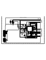
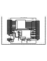
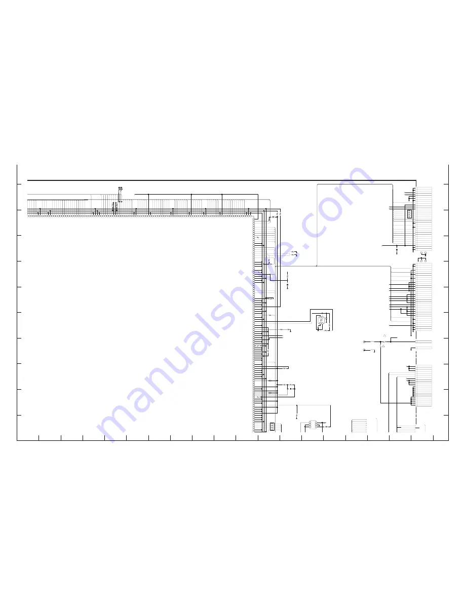
CP1 BOARD (DMA)  MAIN  [UPPER-RIGHT]

ZBOOT_COMREQ

PLLEN

SREQ

HOTLINE

VDD3

IAMPPWM

OC_EN

G_RESETN

GDATA

HALL_OFFSET

IRISPWM

OC_CONT

+12V(A)

SW3.2V

0.1;B

0603

C1501

NJM2561F1A

QNJM2561F1A-P

IC151

1

PS

2

OUT

3

SAG

4

IN

5

GND

6

VCC

4.7;B

1608

H=1.0

C1503

VDD1.8

2.2;1/16J

R1046

EV1MSSA

QEV1MSSA----N

IC101

P8

VDD1

N11

VSS1

V10

GPOF2

U10

GPOF1

AB11

GPOF0

Y4

AVDD33D_VDAC

W4

AVSS33D_VDAC

AA11

VOUT

W5

AVSS33A3_VDAC

Y5

AVDD33A3_VDAC

V11

UOUT

W6

AVSS33A2_VDAC

Y6

AVDD33A2_VDAC

U11

YOUT

W7

AVSS33A1_VDAC

Y7

AVDD33A1_VDAC

W8

AVSS33AR_VDAC

U12

IREFV

V12

VREFV

AA12

COMPV

Y8

AVDD33AR_VDAC

W9

AVSS33D_ADAC

Y9

AVDD33D_ADAC

AB12

AOUT

U13

VREFAO

V13

COMPAO

R8

VDD1

N12

VSS1

R10

VDDQ

P10

VSSQ1

W10

AVSS33A_ADC

Y10

AVDD33A_ADC

Y11

VREFAI

U14

CH0

V14

CH1

U15

CH2

V15

CH3

R11

VDDQ

P11

VSSQ1

P14

VDD1

N13

VSS1

W11

VSSUSB2

Y12

VDD12USB2

Y13

VDDA33T1

W12

VSSA33T1

AB14

DP

W13

VSSA33T2

AB15

DM

W14

VSSA33T3

Y14

VDDA33T2

AA13

REXT

Y15

VDDA33C1

W15

VSSA33C1

AB17

XI

AB18

XO

R12

VDDQ

P12

VSSQ1

AB13

VBUS

W16

AVSS12D_CPLL

Y16

AVDD12D_CPLL

W17

AVSS12A_CPLL

Y17

AVDD12A_CPLL

W18

AVSS12D_APLL

Y18

AVDD12D_APLL

W19

AVSS12A_APLL

Y19

AVDD12A_APLL

U16

GPOB6

V16

GPOB5

AA15

GPOB4

AA14

GPIOB3

U17

GPIOB2

V17

GPIOB1

AA16

GPIOB0

R13

VDDQ

P13

VSSQ1

R14

VDD1

M14

VSS1

AB16

ZRST

V18

CKIN

AA18

D4CKIN

AA17

D4CKOUT

U19

TEST1

V19

TEST0

AA19

MVCK54M

AB19

MCLK

V20

CLKSEL

W20

PSELCCD

Y20

PSELSYS

AA20

PLLEN

AB20

ZSREQ

Y22

SCK

N15

VDDQ

N14

VSSQ1

Y21

SDI

W22

SDO

W21

SRCLK

V22

CKRE

V21

ZRCE

U22

ZRAS

U21

ZCAS

U20

ZRWE

U18

SA14

T22

SA13

T21

SA12

T20

VDDQRA

M15

VSSQRA

R15

VDD1

M13

VSS1

T19

SA11

T18

SA10

T17

SA9

R22

SA8

R21

SA7

R20

SA6

R19

SA5

R18

SA4

R17

SA3

P22

SA2

P21

SA1

P20

VDDQRA

L15

VSSQRA

P19

SA0

P18

SD31

P17

SD30

N22

SD29

N21

SD28

N20

SD27

P15

VDD1

M12

VSS1

N19

SD26

N18

SD25

N17

SD24

M22

SD23

M21

SD22

M20

VDDQRA

M19

VSSQRA

M18

SD21

M17

SD20

L17

SD19

L18

SD18

L19

SD17

L20

SD16

L21

SD15

K14

VDD1

L14

VSS1

L22

SD14

K17

SD13

K18

SD12

K19

SD11

K20

SD10

K21

SD9

K22

SD8

J17

SD7

J18

SD6

J19

VSSQRA

J20

VDDQRA

J21

SD5

J22

SD4

H17

SD3

H18

SD2

H19

SD1

K15

VDD1

L13

VSS1

H20

SD0

H21

DQM3

H22

DQM2

G17

DQM1

G18

DQM0

G19

TSEL1

G20

TSEL0

G21

RTCK

G22

TCK

F17

TRST

F18

TMS

F19

TDO

F20

TDI

F21

ZCS0

F22

GPOA2

E18

ZWE

E19

VSSQ1

E20

VDDQ

J14

VDD1

K13

VSS1

E21

ZRE

E22

A22

D19

A21

D20

A20

D21

A19

D22

A18

C20

A17

C21

A16

C22

A15

A20

A14

B20

A13

A19

A12

B19

A11

C19

A10

A18

A9

B18

A8

C18

A7

D18

A6

A17

A5

B17

A4

C17

VDDQ

D17

VSSQ1

E17

A3

A16

A2

B16

A1

J15

VDD1

K12

VSS1

C16

D15

D16

D14

E16

D13

F16

D12

A15

D11

4
3

EN
Q

TA7
TA6
TA5
TA4
TA3

TA2
TA1
TA0

G

Q

TA

K

LK

LK

TCLK

7
6
5
4
3
2
1
0

7

8
9
0
1
2
3
4
5
6
7
8
9

40
41
42
43
44

45

26
25
24
23

22
18
17
16

7
6
5
4
3
2
1
0

0;1/16Z

1608

R1023

0;1/16Z

1608

R1024

48.000MHz

1AV4V10B6840G

X1102

1

2

3

4

1;B

C1051

470;1/16D

R1121

22;1/16J

R1013

0;1/16Z

1608

R1008

0;1/16Z

R1047

4.7;B

1608

C1001

1M;1/16J

R1122

31

1AV4J11VR310G

CN103

10

LCD_AN

4

MIC_R+

11

LCD_CA

5

A_GND

12

LCDSD

6

A_GND

13

LCDCK

7

GND

14

LCDEN

8

MR_PANEL_TURN

15

LCDRESET

9

VDD3

16

VD

17

HD

18

GND

19

LMCLK

20

GND

1

GND

2

GND

3

MIC_L+

21

LCDD7

22

LCDD6

23

LCDD5

24

LCDD4

25

LCDD3

26

LCDD2

27

LCDD1

28

LCDD0

29

VDD3

30

GND

31

GND

Z1

Z2

VDD3

10K;1/16J

R1061

1000P;B

C1061

20

1AV4J10JR200G

CN105

10

+12V(A)

4

ZCHGDONE

11

GND

5

CHG

12

GND

6

FLCTL

13

GND

7

SW3.2V

14

GND

8

+12V(A)

15

GND

9

+12V(A)

16

UNREGST

17

UNREGST

18

UNREGST

19

UNREGST

20

UNREGST

1

AL3.2V

2

AL3.2V

3

AL3.2V

0;1/16Z

1608

R1055

VDD3

0

RB161

1

2

3

4

5

6

7

8

LCD_AN

LCD_CA

LCD_AN

LCD_CA

BACKUP_BAT

BOOST5.3V

+12V(A)

-6.0V(A)

+3.4V(A)

VDD1.2

VDD3

VDD1.8

USBD+

USBD-

A_GND

MIC_L+

MIC_R+

D0.5

CL156

D0.5

CL155

AWG26/24

JW502

1

GND

AWG26/24

JW501

1

UNREG_V

2A32V

F88K2R0D3MFFD

F5101

1

2

2.5A24V

F88K2R5DAMFFD

F5102

1

2

UNREGSY

AL3.2V

220

RB113

5

6

3

4

7

8

1

2

0.1;B

0603

C1774

0.1;B

0603

C1053

0.1;B

0603

C1052

1.6K;1/20D

0603

R1051

1K;1/20D

0603

R1052

R1033

100;1/20D

0603

3.3K;1/20D

0603

R1036

0;1/20Z

0603

R1031

0;1/20Z

0603

R1001

0;1/20Z

0603

R1015

0;1/20Z

0603

R1002

0;1/20Z

0603

R1017

0;1/20Z

0603

R1019

10K;1/20J

0603

R1042

10K;1/20J

0603

R1043

R1021

10K;1/20J

0603

R1022

10K;1/20J

0603

P_GND

33

1AV4J11VR330G

CN104

10

VDD3

4

GND

11

VDD1.8

5

SP+

12

VDD3

6

GND

13

LCD_AN

7

SP-

14

VDD1.2

8

VDD3

15

-6V(A)

9

VDD1.8

16

VDD1.2

17

+12V(A)

18

VDD1.2

19

PAON4

20

BOOST5.3V

1

GND

2

GND

3

BACKUP_BAT

21

+3.4V(A)

22

BOOST5.3V

23

LCD_CA

24

BOOST5.3V

25

BLON

26

27

PON

28

29

PAON

30

31

PAON2

32

GND

33

GND

Z1

Z2

3.9K;1/20D

0603

R1053

75;1/16D

R1502

8P;CH

C1121

8P;CH

C1122

FBMH1608HL300

1608

L5102

FBMH1608HL300

1608

L5101

SREQ

ZBOOT_COMREQ

PLLEN

HOTLINE

IRISPWM

G_RESETN

HALL_OFFSET

OC_CONT

OC_EN

IAMPPWM

GDATA

SREQ

A5

CKRE

SA13

SA9

SD1

ZRCE

SA11

XSG3

SA0

ZRAS

SD25

SD24

SD2

ZCAS

A8

A11

SD30

A3

ZRWE

SA7

SD0

A4

TSEL

SD26

XIN

XIN

XSG1

ZFRD

D15

SD7

SD6

SD31

RTCK

SD13

TMODE

A6

SD29

DQM2

SA5

A9

XSG2

TRST

SD20

TCK

ASIC_SDO

A15

TMS

SD14

SD4

TDO

A7

TDI

A16

ZCS0

SD8

D12

ZFWR

A12

DQM1

A2

SD18

SD11

SA12

HALL_OUT

A10

SD17

SCK

SD9

D14

SD3

SD19

XOUT

XOUT

D11

SD12

A1

D13

SA3

SA10

SD5

A13

SA8

VBDET

SD10

SD22

ASIC_SDI

DQM0

SA6

YOUT

SD16

SA2

SD15

SUBCNT

SA1

CKRAM

SD23

SA4

SD28

DQM3

SD21

A14

SD27

TXD0

INT_ONENAND

ZCS1

A17

A18

A19

A20

LCDRESET

LCDEN

LCDCK

LCDSD

MRPANEL_TURN

LCDVD

LCDHD

LMCLK

LCDD7

LCDD6

LCDD5

LCDD0

LCDD1

LCDD2

LCDD3

LCDD4

PW_BAT-

UNREGST

ZCHGDONE

CHG

FLCTL

MRST

PAON2

PON

BLON

PAON4

PAON

SP+

SP-

BAT+

BAT-

BL

RD

SYSTEM ASIC

TO VF1

CN172

TO PW1  CN501

TO PW1  JW501

TO PW1  JW502

TO ST1

CN541

!

!

GND

GND

GND

VIDE DRIVER

3.4

5.3

12

1.2

3.3

-6.0

1.8

Summary of Contents for VPC-CA65EXBL

Page 1: ...ode 168 094 01 U S A Canada VPC CA65EXW Product Code 168 094 02 Europe U K South America China Australia Hong Kong Russia Middle East Africa General Korea Taiwan RoHS This product does not contain any hazardous substances prohibited by the RoHS Directive WARNING You are requested to use RoHS compliant parts for maintenance or repair You are requested to use lead free solder This product has been m...

Page 2: ...0 C 662 F or less for chip compo nents to 380 C 716 F for lead wires and similar and to 420 C 788 F when installing and removing shield plates The tip of the soldering iron should have a C cut shape or a driver shape so that it can contact the circuit board as flat or in a line as much as possible Solder Use solder with the metal content and composition ratio by weight given in the table below Do ...

Page 3: ...Horizontal 28 Vertical 7 1 23 24 4 7 8 9 11 5 6 10 14 V1 V3A V3B V1S V2 V3R V3L V4 Vertical shift register clock pulse Vertical shift register clock pulse CCD output 6 0 V 0 V 12 V Aprox 10 V Vertical shift register clock pulse VO V5R V5L V6 6 0 V 0 V 6 0 V 0 V GND Reset pulse GND Power DC 12 V GND 0 V 12 5 V 16 V ØRG 13 16 12 15 VDD DC Protection P well 6 0 V PT DC ØH1 ØH2 Horizontal shift regist...

Page 4: ...r It is con verted internally into a small amplitude actuating signal LVDS and is then input to IC101 The gain of the VGA am plifier is controlled by pins 32 33 and 34 using serial signals which is output from IC101 1 3 32 33 31 30 37 38 35 36 34 42 43 44 39 40 41 4 26 13 14 12 11 SUBCNT VDC CH1 V1 V6 V4 V5R V5L V3R V3L V1S CH5 V5 CH3 CH4 V3 CH2 GND VH OV3B OV3A OV5B OV5A Level conversion 29 V2 2 ...

Page 5: ... At this time correction of the lens distortion which is a characteristic of wide angle lenses is carried out After AWB and γ processing are carried out a matrix is generated and aperture correction is carried out for the Y signal and the data is then compressed by JPEG and is then written to card memory SD card When the data is to be output to an external device it is taken data from the memory a...

Page 6: ...rom the ASIC IC101 are con verted into drive pulses FOCUS A FOCUS A FOCUS B and FOCUS B by the motor driver IC951 and are then used to drive micro step the stepping motor for focusing op eration Detection of the standard focusing positions is carried out by photointerruptor F_SENSE inside the lens block 4 2 Zoom drive The three control signals LENS_SD LENS_CK and LENS_EN which are output from ASIC...

Page 7: ...l signal P ON are recontrolled to restore output 3 Motor System Power Output 5 3 V is output Feedback for the 5 3 V is provided to the switch ing controller Pin 36 of IC501 so that PWM control can be carried out 4 Digital 3 25 V Power Output VDD3 is output Feedback for the VDD3 is provided to the swiching controller Pin 45 of IC501 so that PWM control can be carried out 5 Digital 1 2 V Power Outpu...

Page 8: ...mer 1 5 Rectifier circuit The high voltage alternating current which is generated at the secondary side of T5401 is rectified to produce a high voltage direct current and is accumulated at electrolytic ca pacitor C5412 1 6 Charge monitoring circuit The functions programmed in the IC541 monitor oscillations and estimate the charging voltage If the voltage exceeds the rated value charging automatica...

Page 9: ...detection L SD card Backup battery charge control L charge Strobo condensor charge done detection H L charge done Hot line request from ASIC Test mode terminal L starting up test mode VDD Red LED H lighting Green LED H lighting OneNAND flash reset L reset LCD backlight ON OFF single H backlight ON Lens driver IC standard clock output System reset MRST UART sending combine with debugger terminal JT...

Page 10: ...n terminal L connection VSS1 UNREG SY I Camera power voltage input 61 62 XOUT O Main clock oscillation terminal 4 MHz VDD1 VDD 51 KEY_POWER I Key input POWER L input 52 KEY_2ND I Key input 2nd SHUTTER L input 55 56 RESET I Microprocessor reset input L reset 57 XCIN I Sub clock oscillation terminal 32 768 kHz 58 XCOUT O Sub clock oscillation terminal 32 768 kHz 60 XIN I Main clock oscillation termi...

Page 11: ...ower switch is turned off so that the camera can start up again When the battery is removed the 8 bit microprocessor operates in sleep mode using the backup battery At this time the 8 bit microprocessor only carries out clock counting and waits in standby for the battery to be attached again When a switch is operated the 8 bit microprocessor supplies power to the system as required The 8 bit micro...

Page 12: ... be supplied as single parts Summary of waterproof maintenance parts kit Parts name COMPL MENT KIT SV 114 Parts code 636 110 2131 NO DESCRIPTION 1 2 3 GASKET CABINET SG114 J 4 1 NUMBER 5 2 SPACER MIC2 SG114 J 1 GASKET LCD SG114 J 6 PAD BATTERY SG114 J 1 ADHESIVE COV BATT A SG114 1 1 ADHESIVE COV BATT B SG114 7 ADHESIVE COV BATT D SG114 1 CABINET LCD COVER BATTERY PARTS NO 6361040174 6361073998 636...

Page 13: ...AL OF CABI LEFT AND PW1 BOARD 1 Screw 1 7 x 2 5 2 Screw 1 7 x 3 5 3 Cover joint base 4 Open the cover battery 5 Screw 1 4 x 2 5 6 Five screws 1 7 x 5 7 Dec grip 8 Button menu 9 Screw 1 7 x 5 10 Screw 1 7 x 3 5 11 Four screws 1 7 x 4 5 12 Cabi left 13 Gasket cabinet 14 Earth dec front 15 Assy fpc gasket 16 Flexible pwb CP1 PW1 17 Spacer holder joint 18 Remove the solder 19 Remove the solder 20 Scre...

Page 14: ...od between steps 8 and 9 on page 13 Tilt the LCD to approximately 45 degrees Next push the ASSY FPC GASKET gently with a finger until the clearance t between the bottom CABINET RIGHT edge of the ASSY FPC GASKET and the CABINET RIGHT is 0 Installing the gasket cabinet step 13 on page 13 Install from directly above in the order of the numbers so that the gasket is not twisted ...

Page 15: ... x 4 5 3 Screw 1 7 x 6 4 Holder PW1 5 Holder lens 6 Spacer lens left 7 Spacer CA1 2 2 REMOVAL OF LENS ASSEMBLY AND CA1 BOARD When assembling assemble order a b c When assembling assemble order A B 8 Connector 9 Two FPCs 10 Lens assy 11 Spacer CA1 B 12 Three screws 1 4 x 3 5 13 CA1 board ...

Page 16: ... A B D D A C E E C G G 1 2 3 4 5 6 7 8 9 10 11 12 13 14 15 16 17 18 19 20 21 22 23 24 25 26 27 28 29 30 31 32 33 34 A C B 2 3 REMOVAL OF CP1 BOARD AND ST1 BOARD When assembling tighten the screws order A B C ...

Page 17: ... 12 FPC 13 Spring batt eject 14 Terminal batt 15 Cover triger 16 Spacer ST1 17 Two screws 1 7 x 2 18 Connector 19 ST1 board 20 Remove the solder 21 Spacer H flash B 22 Assy lamp 23 Screw 1 7 x 2 24 Earth PW1 25 Screw 1 7 x 2 26 Screw 1 7 x 2 27 Holder CP1 2 28 Holder CP1 29 Two screws 1 7 x 6 30 Assy holder strap 31 Gasket strap 32 Screw 1 7 x 3 5 33 Spring lock lever 34 Lever batt lock 16 3 4 1 ...

Page 18: ...1 22 22 23 24 25 26 27 28 29 30 30 2 4 REMOVAL OF LCD AND VF1 BOARD When assembling tighten the screws order A B C When assembling tighten the screws order a b c d When assembling tighten the screws order A B 3 4 2 1 Installing the gasket LCD step 36 Install from directly above in the order of the numbers so that the FPC is not twisted ...

Page 19: ...int R 24 Holder joint L 25 Pull the assy joint from the LCD 26 Four screws 1 7 x 3 27 Cover LCD inner 28 FPC 29 FPC 30 Four screws 1 7 x 2 5 31 FPC 32 LCD 33 Three screws 1 7 x 2 34 VF1 board 35 Holder LCD 36 Gasket LCD 37 Cover LCD front 38 Assy joint Installing the ASSY JOINT RUBBER to the COVER LCD FRONT step 28 Install so that the rubber will not come out Installing the LCD to the CABI RIGHT s...

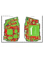
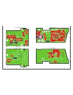
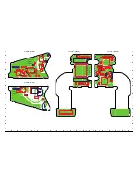
Page 20: ... 20 2 5 BOARD LOCATION PW1 board CA1 board CP1 board ST1 board VF1 board ...

Page 21: ...uminosity to 900 20 cd m2 Be careful of handling the lump and its circumference are high temperature during use and after power off for a while 4 Computer screen during adjustment 3 5 Connecting the camera to the computer This camera requires a DC adaptor sold separately in order to use an AC adaptor 1 Insert the DC adaptor to the camera 2 Insert the AC adaptor s cable to DC terminal of the DC ada...

Page 22: ...tions below they are determined as within specifications Adjustment value determination 1800 STD_AFPOS 2000 100 focus1 100 100 focus2 100 100 focus3 100 200 focus4 200 lens_error 0 Camera Collimator 3 6 The adjustment item which in necessary in part exchange COMPL PWB CP 1 Lens Adjustment AWB Adjustment CCD White Point Defect Detect Adjustment CCD Black Point And White Point Defect Detect Adjustme...

Page 23: ...1 220 100 s2 220 100 s3 220 100 s4 220 100 s5 220 ms4 ms3 ms2 ms1 s1 s2 s3 s4 s5 Adjustment values other than the above are irrelevant 3 CCD White Point Defect Detect Adjustment Preparation POWER switch ON Adjustment method 1 Double click on the DscCalDi exe 2 Select CCD Defect on the LCD Test and click the Yes 3 After the adjustment is completed OK will display 4 Click the OK 4 CCD Black Point An...

Page 24: ...Keep MENU button SET button and SHUTTER button de pressed while switching on the power 2 Connect the camera and the computer with USB cable 3 13 Firmware uploading procedure 1 Uploading the firmware should be carried out if the version number COMPL PWB XX X on the replacement circuit board is lower than the version of the distributed firmware For XX X enter the name of the circuit board containing...

Page 25: ...nd check the USB storage data VID SANYO PID CA65 Serial Rev 1 00 4 Check the Serial in the above USB storage data If the displayed value is different from the serial number printed on the base of the camera enter the number on the base of the camera Then click the Set button 5 Next check VID PID and Rev entries in the USB storage data If any of them are different from the values in 3 above make th...

Page 26: ...Y INPUT CHECK UNIT SW IC501 26 32 30 31 P ON PAON PAON2 CHECK IC101 IC301 PWA BLOCK CAA BLOCK SERIAL COMMUNICATION CHECK IC301 CP1 DMA BLOCK CHECK CP1 DMA BLOCK TAKING INOPERATIVE HIGH LOW LOW LOW NO NO LOW HIGH HIGH HIGH YES YES YES HIGH OK NO LOW NG NO PICTURE MAIN CLOCK FOR SYSTEM OPERATION NO OPERATION IF ABSENT CHECK X1102 OSCILLATOR IC101 AB18 XOUT CHECK OSCILLATION IC301 63 64 ASIC_SO ASIC_...

Page 27: ...27 MEMO ...

Page 28: ... CASE SOFT SG114 J 3 645 087 1818 CABLE DSC USB 4 645 087 1825 CABLE DSC A V 5 645 089 5074 BATTERY CHARGER VPC E1W VPC E1BL VPC E1YL OR 645 093 9624 BATTERY CHARGER VPC E1W VPC E1BL VPC E1YL 6 645 083 6787 CORD POWER 1 2MK VPC CA65EXW VPC CA65EXBL VPC CA65EXYL 7 645 089 5081 BATTERY CHARGER EXCEPT VPC E1W VPC E1BL VPC E1YL OR 645 093 9617 BATTERY CHARGER EXCEPT VPC E1W VPC E1BL VPC E1YL 8 645 089...

Page 29: ...29 1 1 2 3 3 4 5 5 6 6 7 7 8 8 9 ACCESSORIES ...

Page 30: ...E PWB CP1 PW1SG114 20 636 106 3708 SPACER HOLDER JOINT SG114 21 412 076 4408 WASHER V 1 4X3X0 3 22 636 104 2055 COMPL PWB PW 1 23 636 106 3739 SPACER PW1 SG114 J 24 636 104 3809 HOLDER PW1 SG114 J 25 636 104 0242 HOLDER LENS SG114 J 26 636 104 9498 SPACER LENS DUST SG114 J 27 636 104 7388 SPACER CA1 SG114 J 28 636 106 6808 SPACER LENS LEFT SG114 J 29 645 089 3117 LENS ASSY 30 636 107 2526 SPACER F...

Page 31: ...e parts A A B B 41 N S P 1 2 112 112 39 38 28 37 109 9 104 10 101 104 108 106 107 21 14 12 13 23 22 36 20 35 34 29 24 40 27 19 3 106 20 103 27 30 103 103 103 103 101 102 4 104 104 103 11 15 18 16 17 7 6 31 32 111 110 5 105 33 26 8 42 25 CABINET AND CHASSIS PARTS 1 ...

Page 32: ... COVER LCD BACK SG114 J3 VPC CA65EXYL VPC E1YL 24 636 104 0167 DEC LCD TOP SG114 J VPC E1W VPC CA65EXW VPC CA65GXW 24 636 105 5888 DEC LCD TOP SG114 J2 EXCEPT VPC E1W VPC CA65EXW VPC CA65GXW 25 636 109 7192 COMPL COV LCD IN SV SG114 26 636 107 3998 SPACER MIC2 SG114 J 27 636 104 2048 COMPL PWB VF 1 28 636 104 0334 HOLDER LCD SG114 J 29 636 109 7246 ASSY JOINT SV SG114 J 30 645 093 0331 LCD TD025TH...

Page 33: ...E D D C C F F 120 36 116 116 28 31 34 34 102 119 22 23 35 24 102 32 33 30 27 119 119 120 10 20 114 37 38 38 19 101 18 101 102 101 117 117 117 26 117 118 25 118 101 21 101 9 8 7 2 111 113 6 113 1 113 111 111 113 113 29 17 20 114 37 11 14 16 14 13 12 3 4 5 121 115 15 101 101 ...

Page 34: ... VA301 308 050 0507 VARISTOR AVR M1005C080MT VA302 308 050 0507 VARISTOR AVR M1005C080MT INDUCTORS L1001 945 059 8112 IMPEDANCE 1000 OHM P L1002 945 059 8112 IMPEDANCE 1000 OHM P L1003 945 059 8112 IMPEDANCE 1000 OHM P L1004 945 059 8112 IMPEDANCE 1000 OHM P L1005 945 059 8112 IMPEDANCE 1000 OHM P L1201 945 059 8112 IMPEDANCE 1000 OHM P L1210 945 059 8112 IMPEDANCE 1000 OHM P L1301 945 072 7413 IM...

Page 35: ...TWORK 0X4 1 16W RB162 945 028 0710 R NETWORK 10KX4 1 16W RB181 645 078 4224 R NETWORK 0X2 0 063W RB186 645 091 5420 R NETWORK 20KX2 0 063W RB188 645 078 5702 R NETWORK 1KX2 0 063W RB301 945 028 0703 R NETWORK 1KX4 1 16W RB302 945 042 8204 R NETWORK 33KX4 1 32W RB304 945 028 0703 R NETWORK 1KX4 1 16W RB305 945 028 0703 R NETWORK 1KX4 1 16W RB306 945 028 0727 R NETWORK 100KX4 1 16W RB311 645 068 640...

Page 36: ...C9031 303 381 8109 CERAMIC 1U K 6 3V N S P C9032 303 397 7608 CERAMIC 1U K 25V N S P C9033 303 397 7608 CERAMIC 1U K 25V N S P C9034 303 397 7608 CERAMIC 1U K 25V N S P C9035 303 281 5000 CERAMIC 0 033U K 25V N S P C9036 303 323 6309 CERAMIC 0 1U K 16V N S P C9053 303 338 0309 CERAMIC 0 1U K 10V N S P C9057 303 441 5703 TA SOLID 22U M 10V N S P C9061 303 338 0309 CERAMIC 0 1U K 10V N S P C9064 303...

Page 37: ...ITORS C1701 303 381 8109 CERAMIC 1U K 6 3V C1702 303 433 1102 CERAMIC 1U K 10V C1703 303 382 7804 CERAMIC 2 2U K 10V C1704 303 382 7804 CERAMIC 2 2U K 10V C1705 303 382 7804 CERAMIC 2 2U K 10V C1706 303 382 7804 CERAMIC 2 2U K 10V C1707 303 281 2405 CERAMIC 0 22U K 16V C1708 303 281 2405 CERAMIC 0 22U K 16V C1709 303 383 5007 CERAMIC 1U K 16V C1710 303 383 5007 CERAMIC 1U K 16V C1711 303 338 0309 ...

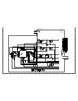
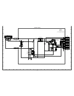
Page 38: ...7 STROBE CIRCUIT C7 SYSTEM CONTROL CUIRCUIT C8 CIRCUIT DIAGRAMS CIRCUIT WAVEFORMS C8 CP1 BOARD DMA MAIN C9 CP1 BOARD TCA LENS C14 CP1 BOARD SYA SYSTEM CONTROL C15 VF1 BOARD LCD CONNECTOR MIC C16 PW1 BOARD POWER C17 ST1 BOARD STROBE C18 CA1 BOARD CCD C19 PRINTED WIRING BOARDS P W B CP1 P W B SIDE A B C20 VF1 P W B SIDE A B C21 PW1 P W B SIDE A B C21 ST1 P W B SIDE A B C22 CA1 P W B SIDE A B C22 ...

Page 39: ...IATE FROM THE RESISTANCE WATTAGE AND VOLT AGE RATINGS SHOWN EXPLANATORY NOTES EXAMPLES Resistor 10K 1 16J means 10kilo ohm 5 1 16watt max 1M 1 10K means 1mega ohm 10 1 10watt max Capacitor 0 047 F means 0 047micro farad Ftype Electrolytic capacitor 10 16 means 10micro farad 16volt max Inductor 330 J means 330micro henry 5 470 K means 470micro henry 10 No description J or K means 5 Figure of printe...

Page 40: ... GND 2 XV3 3 XV4 21 ADCK 22 GND 23 GND 24 AFECKN 25 AFECKP 26 AFESD1N 27 AFESD1P 28 AFESD2N 29 AFESD2P 30 GND 31 PAON3 32 SUBGT 33 XSG5 34 XSUB 35 XV11 36 XSG1 37 XSG4 38 XV8 39 XV9 40 XV7 41 XV10 42 XSG3 43 SUBCNT 44 GND Z1 Z2 Z3 Z4 CN501 CL155 CL156 10 BOOST5 3V 4 GND 11 LCD_CA 5 PAON 12 BOOST5 3V 6 GND 13 3 4V A 7 PON 14 BOOST5 3V 8 GND 15 PAON4 9 BLON 16 VDD1 2 17 12V A 18 VDD1 2 19 6V A 20 VD...

Page 41: ...301 LC87F2832AUFL64TBM 8bit MICRO PROCESSOR TH301 TEMPERATURE SENSOR IC101 SYSTEM ASIC IC951 BU2233GU LENS DRIVER IC971 AK7331 HALL SENSOR CN951 LENS X5 CN171 2 5inch CN173 FPC TB1 CN302 FPC POWER LCD MIC L XENON TUBE IC183 AK4646EN STEREO CODEC CN301 FPC BACK LED RED LED GREEN ELECTRONIC FLASH MAIN CAPACITOR MAIN CLOCK X3001 X3002 4 000MHz SUB CLOCK 32 768KHz USBDET ZCARD IC903 VIDEO KEY INPUT LE...

Page 42: ...pin HALL_OFFSET IC101 D7pin OC_EN IC101 A7pin OC_CONT IC101 B7pin HALL_OUT IC101 V14pin G_RESETN IC101 AB4pin NDON IC101 G6pin NDOFF IC101 B3pin LENS_EN IC101 B8pin LENS_CK IC101 C8pin LENS_SD IC101 A8pin LENS_RESETN IC101 V5pin STATE2 IC101 A4pin STATE1 IC101 D3pin LENS_4M IC301 G1pin LENS MODE IC101 F7pin SHUTTER IC101 A3pin ZOOM MOTOR FOCUS MOTOR SPRING IRIS SHUTTER ND FILTER ZOOM_A ND ZOOM_B 2...

Page 43: ...G4 XSG5 U10 V10 AA10 AB10 U9 CCDEN CCDSD CCDCK V3 AA3 AB9 AFECKN AFECKP U2 U1 AFESD2P AFESD2N AFESD1P AFESD1N W1 W2 V2 V1 TGVD TGHD Y1 Y2 HALL_OFFSET IRISPWM IAMPPWM GDATA G_CLK G_EN C5 E5 D5 D7 K3 K2 LENS_ RESETN SD CK EN MODE SHUTTER NDON NDOFF G6 B3 A3 V5 A8 C8 B8 F7 AUDMCLK LINE_R LINE_L BITCLK LRCK AUDEN AUDCK AUDSD DACDAT ADCDAT SDDAT 0 3 SDCMD SDCLK VBDET DM DP E2 E1 D2 D1 C2 F3 AB14 AB15 A...

Page 44: ...PAON PAON2 BLON IC504 L5010 VDD1 8 SW REG IC501 SWITCHING CONTROL UPD168802K8 4E5 E1 13 20 21 6 5 2 4 3 1 4 1 4 10 15 SHDNB4 31 16 LOUT3 LOUTA 21 22 LOUTB 21 22 28 SHDNB7 4 5 6 7 26 CTL1 30 SHDNB5 32 SHDNB2 SG114_PW_BLOCK 16 20 7 6 5 4 1 3 UNREGST SW3 2V FLCTL CHG ZCHGDONE AL3 2V CN541 TO CP1 DMA CN105 C5412 C5401 T5401 T5402 D5402 Q5402 POWER FILTER OSCILLATION TRANSFORMER BLOCK RECTIFIER CIRCUIT...

Page 45: ...2 NJU7286ARB1 BATTERY BACKUP STANDBY LED FPC BACK AL3 2V 52 43 24 32 KEY_2nd KEY_MENU KEY_1st KEY_RIGHT MR SENSOR 16 TH301 TEMP SENSOR P ON 30 KEY_DOWN WIDE 33 KEY_SET 31 KEY_LEFT 29 KEY_UP TELE 34 KEY_VREC 27 51 KEY_PLAY KEY_POWER MR SENSOR 20 MR_PANEL_OPEN TO FPC POWER TO DMA TO DMA TCA 64 1 UNREGSY NAND_RESET ZCARD USBDET ZAVJACK HOTLINE MRST ZBOOT_COMREQ SREQ TRST ASIC_SDI ASIC_SDO SCK PON LEN...

Page 46: ...B3 NC B4 NC B5 NC B6 NC B7 VSSo B8 NC B9 A9 B10 A13 B11 NC B12 NC C1 VSSd C2 NC C3 A1 C4 A3 C5 A6 C6 NC C7 VCCo C8 NC C9 A8 C10 A12 C11 NC C12 NC D1 VDD D2 A9 D3 A5 D4 A2 D5 A5 D6 NC D7 NC D8 NC D9 A10 D10 A14 D11 NC D12 DQ15 E1 A4 E2 A8 E3 A7 E4 A11 E5 A4 E6 A7 E7 E8 A15 E9 NC E10 NC E11 DQ14 E12 DQ13 F1 NC F2 CKE F3 A6 F4 DQ29 F5 A0 F6 NC F7 A11 F8 NC F9 NC F10 DQ12 F11 NC F12 DQM1 G1 DQ30 G2 DQ...

Page 47: ...N_2 G15 PIXDAT_IN_3 G16 PIXDAT_IN_4 H15 PIXDAT_IN_5 G14 PIXDAT_IN_6 G13 PIXDAT_IN_7 K14 CCIR656_CLKIN D2 PIXDAT_CCIR656_0 D1 PIXDAT_CCIR656_1 E1 PIXDAT_CCIR656_2 F3 PIXDAT_CCIR656_3 E2 PIXDAT_CCIR656_4 F2 PIXDAT_CCIR656_5 G2 PIXDAT_CCIR656_6 G3 PIXDAT_CCIR656_7 G4 CCIR656_CLKOUT 10K RB162 1 2 3 4 5 6 7 8 VDD1 8 4 7 B 1608 H 1 0 C1018 EV1MSSA QEV1MSSA N IC101 M21 SD22 M20 VDDQRA M19 VSSQRA M18 SD21...

Page 48: ...3 2 1 0 7 8 9 0 1 2 3 4 5 6 7 8 9 40 41 42 43 44 45 26 25 24 23 22 18 17 16 7 6 5 4 3 2 1 0 0 1 16Z 1608 R1023 0 1 16Z 1608 R1024 48 000MHz 1AV4V10B6840G X1102 1 2 3 4 1 B C1051 470 1 16D R1121 22 1 16J R1013 0 1 16Z 1608 R1008 0 1 16Z R1047 4 7 B 1608 C1001 1M 1 16J R1122 31 1AV4J11VR310G CN103 10 LCD_AN 4 MIC_R 11 LCD_CA 5 A_GND 12 LCDSD 6 A_GND 13 LCDCK 7 GND 14 LCDEN 8 MR_PANEL_TURN 15 LCDRESE...

Page 49: ...0 DQ5 M11 VSSQ M12 VDDQ N1 DQ18 N2 DQ19 N3 DQ23 N4 DQ22 N9 N10 DQ3 N11 NC N12 DQM0 P1 DQ16 P2 DQ17 P3 DQ20 P4 DQ21 P5 A10 P6 P7 IO2 P8 IO3 P9 IO11 P10 INTo P11 DQ1 P12 DQ2 R1 NC R2 A3 R3 A1 R4 A0 R5 RDYo R6 IO9 R7 IO10 R8 IO4 R9 IO5 R10 IO13 R11 DQ0 R12 NC T1 NC T2 A2 T3 CLKo T4 T5 IO1 T6 VCCQo T7 VCCQo T8 IO12 T9 VCCQo T10 IO6 T11 IO14 T12 VDD U1 VDD U2 CEo U3 NC U4 NC U5 IO8 U6 NC U7 NC U8 NC U9...

Page 50: ... 1AV4L3DU102PG 1608 L1304 TCM12109002P L1301 1 2 3 4 BK1608LM751 1AV4L26B1150G 1608 L1302 11 GND 12 GND 13 GND 14 GND 15 GND 16 UNREGST 17 UNREGST 18 UNREGST 19 UNREGST 20 UNREGST 100 RB145 3 4 7 8 5 6 1 2 0 RB115 1 2 3 4 5 6 7 8 ZCHGDONE AL3 2V AL3 2V LENS_4M LENS_4M USBD USBD SW3 2V SW3 2V BLON 20K RB186 1 2 3 4 0 1 B C1827 1 B C1832 0 1 B C1831 TK70630HCL G QTK70630HC GG IC187 1 VCOUNT 2 GND 3 ...

Page 51: ... 1 16D R9721 LENS_EN 0 1 B C9526 10 1000P B C9719 100K 1 20D R9719 1K 1 20D R9723 2 2 B 2125 C9534 NDOFF VDD3 23 1AV4J11NV231G CN951 10 DRIVE 4 ZOOM B 11 HALL OUT 5 NC 12 HALL IN 6 ZOOM LED 13 HALL OUT 7 ZOOM VCC 14 HALL IN 8 ZOOM SENSE 15 FOCUS LED 9 DRIVE 16 FOCUS VCC 17 FOCUS SENSE 18 ND 19 ND 20 FOCUS A 1 ZOOM A 2 ZOOM B 3 ZOOM A 21 FOCUS B 22 FOCUS A 23 FOCUS B LENS_MODE 470P B C9718 2 2K 1 2...

Page 52: ...1 SCK 1 B2 2 C3 3 C2 4 D2 HOTLINE 5 C1 TEST_MODE 6 D3 LCD_PWM 7 D1 NC 8 E1 VDD2 9 E2 VSS2 10 F1 VF LED R 11 E3 VF LED G 12 F2 13 E4 NC 14 H1 BL ON 15 G1 LENS_4M 16 H2 17 G2 NC 18 F3 TXD 19 G3 MR_PANEL_OPEN 20 G4 21 H3 PLLEN 22 F4 TRST 23 H4 KEY_1st 24 H5 ST_CHG 25 G5 BOOT_COMREQ 26 H6 KEY_PLAY 27 F5 28 G6 KEY_UP TELE 29 E5 KEY_DOWN WIDE 30 H8 KEY_LEFT 31 H7 KEY_RIGHT 32 G8 KEY_SET 33 G7 KEY_VREC 3...

Page 53: ...1701 100K 1 16J R1703 1 B C1702 2 2 B 10 1608 C1703 2 2 B 10 1608 C1704 2 2 B 10 1608 C1705 2 2 B 10 1608 C1706 0 22 B 16 1608 C1707 0 22 B 16 1608 C1708 1 B 16 1608 C1709 1 B 16 1608 C1710 1 B C1701 2 2 1 16J R1702 TK70630HCL G QTK70630HC GG IC185 1 VCOUNT 2 GND 3 NP 4 VOUT 5 GND 6 VIN A_GND 4 7 B 1608 C1852 SMP0208HD5 SB MIC01 1 VOUT 2 GAIN CTL 3 GND 4 VDD SMP0208HD5 SB MIC02 1 VOUT 2 GAIN CTL 3...

Page 54: ...5071 15K 1 16D R5073 102K 1 16D R5302 430K 1 16D R5303 33 1AV4J11VR330G CN501 10 BOOST5 3V 4 GND 11 LCD_CA 5 PAON 12 BOOST5 3V 6 GND 13 3 4V A 7 PON 14 BOOST5 3V 8 GND 15 PAON4 9 BLON 16 VDD1 2 17 12V A 18 VDD1 2 19 6V A 20 VDD1 2 1 GND 2 GND 3 PAON2 21 LCD_AN 22 VDD3 23 VDD1 8 24 VDD3 25 VDD1 8 26 VDD3 27 SP 28 GND 29 SP 30 GND 31 BACKUP_BAT 32 GND 33 GND Z1 Z2 43K 1 16D R5052 BOOST5 3V BLON PAON...

Page 55: ...TJ IC541 1 SW 2 SW 3 VCC 4 F_ON 5 NC 6 I_PEAK 7 G_IGBT 8 NC 9 XFULL 10 CHG 11 PGND 12 PGND 13 NC 14 NC 15 VBAT 16 NC Z1 AWG28 2 2X1 5 JW541 PINK 1 XAN AWG28 2 2X1 5 JW542 BLACK 1 XKT 0 018 350B 3216 C5410 FV02R80TP D5402 20 1AV4J11JX200G CN541 10 12V A 4 ZCHGDONE 11 GND 5 CHG 12 GND 6 FLCTL 13 GND 7 SW3 2V 14 GND 8 12V A 15 GND 9 12V A 16 UNREGST 17 UNREGST 18 UNREGST 19 UNREGST 20 UNREGST 1 AL3 2...

Page 56: ...C8G Q9001 1 E 2 B 3 G 4 S 5 D 6 C 7P CH C9069 7P CH C9070 27 1 16J R9055 27 1 16J R9051 AWG30 2 0X1 25 JW901 BLACK 1 GND 0 1 16Z R9062 0 1 16Z R9063 REG 3 0V NJM2877F3 03 QNJM2877F303P IC904 1 2 3 4 5 0 1 16Z R9064 0 1 16Z R9065 0 1 16Z R9066 0 1 16Z R9067 330 1 16J R9002 0 1 B C9073 0 1 B C9074 0 01 B C9006 1 B 1608 25V C9032 1 B 1608 25V C9033 MA2S111 D9002 44 1AV4J11JS440G CN901 10 CCDSD 4 XV2 ...

Page 57: ...IC121 CL155 RB302 RB306 CB185 CN104 CN301 RB187 C9513 C1071 CN951 CL310 CL156 RB301 RB312 C1036 C1072 C1073 C1074 C1075 R1070 R1072 R1073 R1074 R1083 R1084 R1085 IC104 F5101 F5102 CL331 CL332 CL333 CL334 CL335 CL336 CL338 R1009 R1011 CL339 SIDE B TEST_MODE GND G9400AA SG114_CP1 CN110 R1064 Q3002 L1001 L1003 L1004 VA131 VA133 VA134 C1038 L1302 L1303 L1304 C1061 R1061 C3001 C3007 Q3004 C3012 R3002 R...

Page 58: ...5004 L5005 L5007 L5010 IC502 IC503 IC504 IC505 CL516 CL501 CL505 D5301 CL529 CL530 C5076 C5077 Q5004 G9500BA SIDE B SG114 PW1 C5011 C5001 C5002 C5003 C5004 C5005 C5006 C5007 C5008 CL526 C5021 C5042 R5021 R5022 R5023 R5041 R5042 C5072 R5071 R5072 R5073 R5074 R5076 C5304 R5301 R5302 R5303 CL503 C5009 CL502 CL504 R5082 D5011 R5077 R5078 D5031 IC501 CL519 CL518 CL515 CL535 CL536 CL533 Q5014 CL534 PW1 ...

Page 59: ...062 D9002 R9066 R9065 C9072 C9073 D9003 C9058 C9061 R9039 C9031 R9035 L9001 C9034 C9035 C9036 C9064 C9070 C9069 R9059 R9058 R9051 C9071 CB904 CB905 CB906 IC901 IC905 Q9001 CL901 CA1 P W B SIDE B SG114 ST1 SIDE A G9500CA CL550 CL553 CL554 R5403 R5405 C5402 D5404 RB541 IC541 CL551 RB542 CL548 R5404 C5404 R5411 C5403 CL549 R5424 Q5402 R5422 C5411 D5401 R5402 CL544 CL547 CL545 CL546 CL556 CL552 CL555 ...

Page 60: ...July 07 SANYO Electric Co Ltd Osaka Japan Printed in Japan ...

Reviews: