– 13 –
2
7
4
1
A
B
16
14
8
9
12
10
11
3
5
a
b
6
13
15
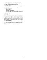
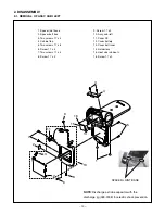
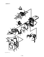
When assembling,
tighten the screws order.
A
→
B
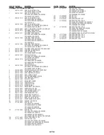
1. Two screws 1.7 x 5
2. Cover joint base
3. Spacer speaker wire
4. Speaker, 8
5. Two screws 1.7 x 4
6. Holder speaker
7. Assy, wire VF1 & CP1
8. Dec bottom
9. Shield tape bottom
10. Spacer CP1 2
11. Spacer button power
12. Heat sink right
13. Shield tape bottom
14. Button power
15. Cover SD
16. Assy, cabi right
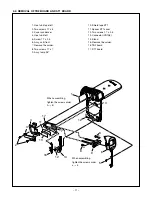
2-4. REMOVAL OF ASSY, CABI RIGHT
When assembling,
tighten the screws order.
a
→
b


