-
13
-
O
K
O
P
N
L
M
K
P
L
N
M
Q
Q
1
8
10
9
2
4
3
12
5
12
6
7
11
13
14
16
18
17
19
19
24
19
20
21
22
23
25
26
27
27
28
A
B
15
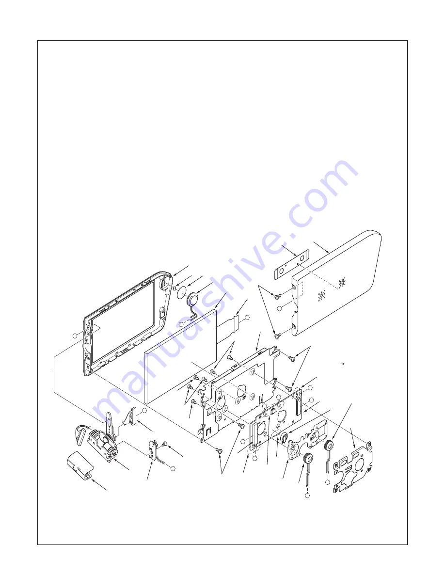
2-3. REMOVAL OF TB1 BOARD, LCD AND VF1 BOARD
1. Cover joint
2. Two screws 1.7 x 3
3. Shield tape MIC
4. Assy, cover LCD back SV
5. Remove the solder.
6. Remove the solder.
7. Connector
8. Assy, joint
9. Assy, shield wire
10. Screw 1.7 x 2
11. TB1 board
(It is cautious of breakage of a switch.)
12. Four screws 1.7 x 2.5
13. Speaker,8
14. Spacer speaker filter
15. Adhesive magnet
16. Assy, cover LCD FR SV
17. FPC
18. LCD
19. Four screws 1.7 x 2
20. Shield VF1
21. Remove the solder.
22. Remove the solder.
23. Battery, recharge
24. Two screws 1.7 x 3
25. VF1 board
26. Assy, HL monitor SV
27. Microphone
28. Holder VF
When assembling,
attachment order.
A B
Summary of Contents for VPC-CG88BK
Page 14: ... 14 2 4 BOARD LOCATION VF1 board ST1 board TB1 board CP1 board ...
Page 23: ...23 1 5 4 2 3 6 7 8 ...
Page 54: ......


