– 18 –
4. Black Point And White Point Defect Detect
Adjustment In Lighted
Preparation:
POWER switch: ON
Setting of pattern box:
Color temperature: 3100
±
20 (K)
Luminance: 900
±
20 (cd/m
2
)
Adjusting method:
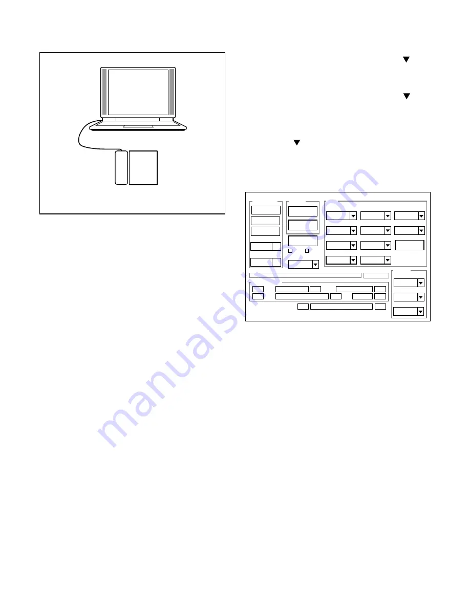
1. Set a distance of 0.5-1.0 cm between the pattern box and
the camera when zoom tele edge.
2. Double-click on the DscCalDi.exe.
3. Select “CCD Black” on the LCD “Test”, and click the “Yes”.
4. After the adjustment is completed, the number of defect
will appear.
5. Click the OK.
Camera
Pattern box
(color viewer)
3-9. Factory Code Setting
1. Check the "Factory Code" display within the Setting group.
2.
For U.S.A., Canada and NTSC general area
If "FC_SANYO_U" does not appear, click on the " " mark
located on the right of the "Factory Code" display BOX and
select "FC_SANYO_U".
3.
For Europe and PAL general area
If "FC_SANYO_EX" does not appear, click on the " " mark
located on the right of the "Factory Code" display BOX and
select "FC_SANYO_EX".
3-10. Language Setting
1. Click on the " " mark located on the right of the
"Language" display BOX.
2. Select language. (Default is English.)
3. End "DscCal" and remove the camera before turning the
camera power OFF.
3-11. Reset Setting
Carry out reset settings after replacing CP1 board.
1. Turn on the camera.
2. Double-click on the DscCalDi.exe.
3. Select “Set Default” on the LCD “Test”.
3-12. The Compulsive boot starting method
1. Keep SHUTTER button depressed while switching on the
power.
2. Connect the camera and the computer with USB cable.
Firmware
Data
AWB
Focus
UV Matrix
R Bright
RGB Offset
Tint
B Bright
Gain
Phase
LCD
Calibration
Upload
Initialize
LCD Type
H AFC
Test
VCOMDC
VCOMPP
Cal Data
Cal Mode
OK
OK
EVF
USB storage
Get
Set
VID
Set
PID
Set
Serial
Set
Rev.
Set
Setting
Language
Video Mode
VCO
Factory Code
Hall Cal.
Backrush pulse :
Set
Get
Summary of Contents for VPC-PD1EXBK
Page 14: ... 14 2 5 BOARD LOCATION TB1 Board ST1 Board CP1 Board ...
Page 21: ... 21 MEMO ...
Page 23: ...2 3 Table of accessories 1 2 ...


