−
2
−
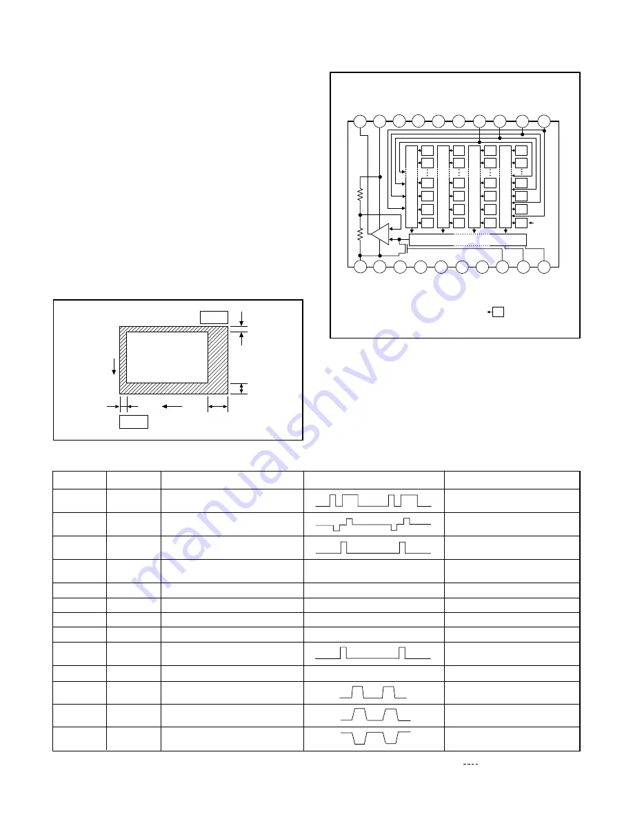
Fig. 1-1.Optical Black Location (Top View)
Pin No.
1
Symbol
2, 3
4
5, 6, 8,
14, 16
7, 9, 12
10
11
13
15
17
18
19
V
φ
1
V
φ
3
NC
GND
V
OUT
V
DD
C
SUB
V
L
φ
RG
H
φ
1
Pin Description
Vertical register transfer clock
Vertical register transfer clock
Vertical register transfer clock
Reset gate clock
Protection transistor bias
Horizontal register transfer clock
GND
Signal output
Circuit power
Substrate clock
Substrate bias
Waveform
DC
Voltage
-8.0 V, 0 V
-8.0 V, 0 V, 15 V
-8.0 V, 0 V
15 V
12 V, 17 V
0 V, 5 V
Table 1-1. CCD Pin Description
φ
SUB
GND
DC
0 V
Aprox. 7 V
Different from every CCD
-8 V
When sensor read-out
Fig. 1-2. CCD Block Diagram
1. OUTLINE OF CIRCUIT DESCRIPTION
1-1. CA1 CIRCUIT DESCRIPTION
Around CCD block
1. IC Configuration
IC903 (ICX245)
CCD imager
IC902 (74ACT04MTC)
H driver
IC907 (CXD3400N)
V driver
IC905 (AD9803)
CDS, AGC, A/D converter
2. IC903 (CCD)
[Structure]
Interline type CCD image sensor
Optical size
1/2 inch format
Effective pixels
1392 (H)
×
1040 (V)
Pixels in total
1434 (H)
×
1050 (V)
Actual pixels
1360 (H)
×
1024 (V)
Optical black
Horizontal (H) direction: Front 2 pixels, Rear 40 pixels
Vertical (V) direction:
Front 8 pixels, Rear 2 pixels
Dummy bit number
Horizontal : 20 Vertical : 3
V
φ
2A,
V
φ
2B
Pin 1
2
8
40
2
H
V
Pin 11
10
9
6
5
4
3
2
1
13
14
15
16
17
18
19
20
G
R
G
R
G
R
B
G
B
G
B
G
G
R
G
R
G
R
B
G
B
G
B
G
Vertical register
Horizontal register
Note
Note:
Photo sensor
V
OUT
GND
NC
NC
V
ø3
øSUB
NC
C
SUB
NC
V
L
øRG
12
GND
11
V
DD
7
GND
8
NC
V
ø2B
V
ø2A
V
ø1
H
ø1
H
ø2
20
H
φ
2
Horizontal register transfer clock
0 V, 5 V
DC
Different from every CCD


