− 17 −
2. Double-click on the DscCalV123b.
3. Click the AWB, and click the Yes.
4. AWB adjustment value will appear on the screen.
5. Click the OK.
6. Color Matrix Adjustment
Preparation:
POWER switch: ON
Adjustment method:
1. Set the color adjustment chart to the color viewer.
(Do not enter any light.)
2. Set the siemens star chart so that it becomes center of
the screen.
3. Double-click on the DscCalV123b.
4. Click the UV Matrix, and Click the Yes.
5. Color matrix adjustment value will appear on the screen.
6. Click the OK.
7. CCD Defect Detect Adjustment
Adjustment method:
1. Double-click on the DscCalV123b.
2. Select CCD Defect on the LCD “Test”, and click the “Yes”.
3. After adjustment, adjustment value will appear on the screen.
8. LCD Panel Adjustment
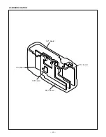
[CA2 board (Side B)]
Serial cable
Camera
15 cm ± 1 cm
All white pattern color
viewer (5,100K) and
color matrix adjustment chart
LCD
adjustment
frame
A
B
LCD screen
FPC
8-1. LCD H AFC Adjustment
Preparation:
POWER switch: ON
Adjusting method:
1. Double-click on the DscCalV123b.
2. Select LCD3 on the “LCD Type”.
3. Select 0 on the LCD “H AFC”.
4. While watching the LCD monitor, adjust LCD “H AFC” so
that the edge of the LCD adjustment frame are the same
distance from the left and right edge of the LCD screen.
(A = B)
8-2. LCD RGB Offset Adjustment
Adjusting method:
1. Adjust LCD “RGB offset” so that the amplitude of the CL403
waveform is 3.40 V
±
0.10 Vp-p.
8-3. LCD Gain Adjustment
Adjusting method:
1. Adjust LCD “Gain” so that the amplitude of the CL403 wave-
form is 1.85 V
±
0.10 Vp-p.
Note:
8-2. LCD RGB Offset adjustment should always be carried
out first.
CL403 waveform
3.40V
±0.10Vp-p
CL403 waveform
1.85V
± 0.10Vp-p
CL403
CL402
CL404
CL420

