background image

− 19 −

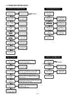
4. TROUBLESHOOTING GUIDE

POWER LOSS INOPERTIVE

BARRIER SW

BARRIER SW ON

NORMAL

IC301-34 (SCAN IN 0)

PULSE INPUT

CHECK POWER SW,

CN303, R3020, D3014

IC302-7 (UNREG)

CHECK ST1, CA2

IC301-25

(VDD)

IC301-21

(RESET)

CHECK IC302

CHECK IC302, R3051

IC301-20

(BAT OFF)

CHECK R3052

IC301-23

OSCILLATION

CHECK X3001,

R3008, C3003, C3004

IC301-26

OSCILLATION

CHECK X3002,

R3004, C3001, C3002

CHECK IC301

NO PICTURE

MAIN CLOCK FOR SYSTEM OPERATION
NO OPERATION IF ABSENT
CHECK X1001 OSCILLATOR AND IC111

CLK (60MHz)

INPUT TO

IC102-18 (CLK IN)

CLK (30 MHz)

INPUT TO

IC101-154 (XTAL 1)

BASIC CPU BLOCK
CHECK ASIC PIN 22

IC102-113 (ZAS)

ALWAYS APPEARS WHEN CPU, ETC. IS ACCESSED
CHECK IF CPU IS READKING PROGRAM, AND
CHECK ADDRESS AND DATA BUS OF IC121

IC101-68
(ZBREQ)

REQUEST FOR USE OF DATA BUS FROM
ASIC TO CPU NO DMA TRANSMISSION IF ABSENT
CHECK IC102-110

IC102-111

(ZBGRNT)

RECEIVES ZBREQ SIGNAL AND GIVES PERMISSION
TO ASIC FOR USE OF DATA BUS
NO DMA TRANSMISSION IF ABSENT / CHECK IC101-70

IC101-141, 142

(IRL1, 2)

CHECK SOLDERING OF

EACH CPU, ASIC AND

MEMORY PIN

INCORRECT HANDSHAKING BETWEEN 4-BIT
CPU AND RS-232C
CHECK EACH INTERFACE

FOCUS INOPERATIVE

PUSH SUTTER

BUTTON

IC301-36, 37

(SCAN IN 2, 3)

PULSE INPUT

CHECK S3029,

R3022, R3023,

D3015, D3016

CN305-8, 11

(P ON, P(A) ON)

CHECK IC301,

Q3005, Q3006, ST1

IC301-6, 7, 8

HIGH

CHECK

IC301, CA2, ST1

SERIAL

COMMUNICATION

CHECK IC301,
R3015, R3032,

Q3003, CA2

CHECK CA2

AFTER LENS ADJ.

THE LENS IS IN

FOCUS

NORMAL

CHECK IC911

CHECK IC102-107

(PPCS)

CHECK CN903

CHECK IC908,

Q9072, Q9073

CHECK LENS

TAKING INOPERATIVE

LOW

CLOSED

NO

LOW

LOW

LOW

NO

NO

OPEN

YES

HIGH

HIGH

HIGH

HIGH

YES

YES

NO

OK

OK

OK

OK

OK

NG

NG

NG

NG

NG

YES

YES

HIGH

YES

OK

NG

OK

OK

NO

LOW

NO

NG

NG

NG

OK

Summary of Contents for VPC-Z380

Page 1: ... to product safety Should any component designated by a symbol need to be replaced use only the part designated in the Parts List Do not deviate from the resistance wattage and voltage ratings shown CAUTION Danger of explosion if battery is incorrectly replaced Replace only with the same or equivalent type recommended by the manufacturer Discard used batteries according to the manufacturer s instr...

Page 2: ...6 V Different from every CCD 8 V 11 5 V When sensor read out Fig 1 2 CCD Block Diagram 1 OUTLINE OF CIRCUIT DESCRIPTION 1 1 CA1 CIRCUIT DESCRIPTION 1 IC Configuration IC903 RJ23J1AA0AT CCD imager IC902 74VHC04MTC H driver IC904 LR366854 V driver IC905 AD9802 CDS AGC A D converter 2 IC903 CCD Structure Interline type CCD image sensor Optical size 1 2 7 inch format Effective pixels 1292 H 966 V Pixe...

Page 3: ...C Circuit and A D Converter The video signal which is output from the CCD is input to Pins 26 and 27 of IC905 There are S H blocks inside IC905 generated from the XSHP and XSHD pulses and it is here that CDS correlated double sampling is carried out After passing through the CDS circuit the signal passes through the AGC amplifier It is A C converted internally into a 10 bit signal and is then inpu...

Page 4: ...e floating diffusion changes in proportion to the quantity of transferred electric charge and becomes CCD output after being received by the source follower The equivalent circuit for the output circuit is shown in Fig 1 7 H1 H2 H1 H2 H1 HOG RG CCD OUT PD Floating diffusion 1 H1 H2 H1 H2 H1 HOG RG CCD OUT PD 2 H1 H2 H1 H2 H1 HOG RG CCD OUT 3 H1 H2 RG CCD OUT 3 5V 0V 3 5V 0V 15 5V 12V Black level R...

Page 5: ...carried out Each pixel is interpolated from the surrounding data as being either Ye Cy Mg and Gr primary color data to produce R G and B data At this time correction of the lens distortion which is a characteristic of wide angle lenses is carried out After AWB and γ processing are carried out a matrix is gen erated and aperture correction is carried out and the data is then compressed by the JPEG ...

Page 6: ... If output is short circuited for the length of time determined by the condenser which is connected to Pin 17 of IC501 all output is turned off The control signal P ON P A ON and LCD ON are recontrolled to restore output 3 Digital 5 V and Analog System Power Output 5 V D 13 V A 7 0 V A and 5 V A are output Feed back for the 5 V D is provided to the switching controller Pins 28 and 29 of IC501 so t...

Page 7: ... current which is generated at the secondary side of T5401 is rectified to produce a high voltage direct current and is accumulated at electrolytic ca pacitor C5412 on the main circuit board 1 6 Voltage monitoring circuit This circuit is used to maintain the voltage accumulated at C5412 at a constance level After the charging voltage is divided and converted to a lower voltage by R5417 and R5419 i...

Page 8: ...ON RS 232C RXD input terminal Serial clock output ASIC Serial data output ASIC Serial data input ASIC Serial communication request singnal L Serial request DIN jack connection detection signal H Connection Reset input Main clock oscillation terminal 1 MHz Main clock oscillation terminal GND VDD Clock oscillation terminal 32 768 kHz Clock oscillation terminal Analog GND input terminal Analog refere...

Page 9: ...us The SY1 circuit board carries out overall control of camera operation by detecting the input from the keyboard and the condition of the camera circuits The 4 bit microprocessor reads the signals from each sensor element as input data and outputs this data to the camera circuits ASIC or to the LCD display device as operation mode setting data Fig 4 1 shows the internal commu nication between the...

Page 10: ... controls the power supply for the overall system The following is a description of how the power supply is turned on and off When the battery is attached a regulated 3 2 V voltage is normally input to the 4 bit microprocessor IC301 by IC302 so that clock counting and key scanning is carried out even when the power switch is turned off so that the camera can start up again When the battery is remo...

Page 11: ...en it 2 Screw 2 x 5 7 Cabinet front 8 Back cabinet 6 Open the cover jack 3 Holder battery 5 Two screws 2 x 5 9 Connector 5 Screw 2 x 5 5 Three screws 2 x 5 10 FPC 4 Screw 2 x 5 A B A 1 Three screws 2 x 5 2 Three connectors 3 Terminal board 4 Two connectors 5 PW1 board 6 Screw 2 x 5 7 Connector 8 Connector 9 SY1 board 6 Two screws 2 x 5 ...

Page 12: ...ws 2 x 5 2 Lens VF 3 Two screws 2 x 5 4 Holder chassis 5 Screw 2 x 5 6 Housing battery A 8 CA2 board 7 Housing battery B 1 Two screws 2 x 6 2 Screws 2 x 4 3 FPC 4 Two connectors 5 CA1 board 6 Screw 2 x 5 6 Two screws 2 x 5 7 Screw 1 7 x 4 5 8 Pull it 9 FPC 10 LCD 11 Screw 1 7 x 4 5 12 SY2 board ...

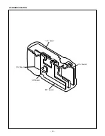
Page 13: ... 13 2 5 BOARD LOCATION SY1 board PW1 board CA1 board SY2 board CA2 board ...

Page 14: ... 3 4 Setup 1 System requirements Windows 95 or 98 IBM R compatible PC with 486 or higher processor CD ROM drive 3 5 inch high density diskette drive Serial port with standard RS 232C interface 8 MB RAM Hard disk drive with at least 15 MB available VGA or SVGA monitor with at least 256 color display 2 Installing calibration software 1 Insert the calibration software installation diskette into your ...

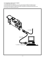
Page 15: ...over on the side of the camera Press on the arrows and slide the cover down to open it 3 Line up the arrow on the cable connector with the notch on the camera s serial port Insert the connector 4 Line up the serial connector on the cable with one of the serial ports on your computer and insert the connector 5 Turn on the camera and your computer system ...

Page 16: ... illumination with no flicker Illumination above the subject should be 400 lux 10 Adjustment method 1 Set the siemens star chart 69 cm 3 cm so that it be comes center of the screen 2 Double click on the DscCalV123b 3 Click the Focus and click the Yes 4 Lens adjustment value will appear on the screen 5 Click the OK 5 AWB Adjustment Preparation POWER switch ON Adjusting method 1 When setting the cam...

Page 17: ...Adjustment CA2 board Side B Serial cable Camera 15 cm 1 cm All white pattern color viewer 5 100K and color matrix adjustment chart LCD adjustment frame A B LCD screen FPC 8 1 LCD H AFC Adjustment Preparation POWER switch ON Adjusting method 1 Double click on the DscCalV123b 2 Select LCD3 on the LCD Type 3 Select 0 on the LCD H AFC 4 While watching the LCD monitor adjust LCD H AFC so that the edge ...

Page 18: ...03 VG waveform Note 8 2 LCD RGB Offset adjustment and 8 3 LCD Gain adjust ment should always be carried out first 8 6 LCD VcomPPAdjustment Adjusting method 1 Adjust LCD VCOMPP so that the amplitude of the CL420 waveform is 5 40 V 0 25 Vp p CL403 waveform VG CL404 waveform VG 0 05 Vp p VG 0 1 0 05 Vp p CL403 waveform VG CL402 waveform CL420 waveform 5 40V 0 25Vp p 8 7 LCD VcomDC Adjustment Adjustin...

Page 19: ... REQUEST FOR USE OF DATA BUS FROM ASIC TO CPU NO DMA TRANSMISSION IF ABSENT CHECK IC102 110 IC102 111 ZBGRNT RECEIVES ZBREQ SIGNAL AND GIVES PERMISSION TO ASIC FOR USE OF DATA BUS NO DMA TRANSMISSION IF ABSENT CHECK IC101 70 IC101 141 142 IRL1 2 CHECK SOLDERING OF EACH CPU ASIC AND MEMORY PIN INCORRECT HANDSHAKING BETWEEN 4 BIT CPU AND RS 232C CHECK EACH INTERFACE FOCUS INOPERATIVE PUSH SUTTER BUT...

Page 20: ... 19 636 051 4959 COVER PLATE SR5 J 20 636 051 8285 COVER JACK SR46 EX 21 636 049 5968 STAND SR4 J STAND 22 636 056 0147 SPACER MONITOR SR813 E 23 636 051 3204 HOLDER KNOB MONITOR SR5 J 24 636 049 9270 ASSY FLEXIBLE PWB MODE SW 25 636 049 5869 HOLDER GLIP SR4 J 26 636 049 5975 SHAFT STRAP SR4 J 27 636 055 9912 ASSY CABI BACK SR813 E 28 636 051 3259 KNOB MONITOR SR5 J 29 636 050 4936 SPACER MODE SR4...

Page 21: ...028 0474 OPTICAL FILTER 13 636 052 0172 SPACER SXGA 14 409 460 0207 IC RJ23J1AA0AT 15 636 048 2296 MOUNTING LENS 16 636 048 2319 SPACER INSULATOR 17 636 055 7918 COMPL PWB CA 1 18 636 055 7925 COMPL PWB SY 1 19 636 055 7765 HOLDER MONITOR SR813 E 20 636 055 7932 COMPL PWB SY 2 21 645 037 5071 LCD 104 411 170 8602 SCR S TPG PAN 2X5 106 411 173 7008 SCR S TPG PAN PCS 1 7X4 5 107 411 022 7807 SCR S T...

Page 22: ... C9018 403 155 1807 CERAMIC 0 01U K 25V C9019 403 320 5500 CERAMIC 1U Z 25V C9023 403 320 5302 CERAMIC 0 15U K 25V C9025 403 338 4403 CERAMIC 0 1U K 16V C9026 403 338 4403 CERAMIC 0 1U K 16V C9027 403 338 4403 CERAMIC 0 1U K 16V C9029 403 338 4403 CERAMIC 0 1U K 16V C9030 403 345 4304 TA SOLID 22U M 10V C9031 403 338 4403 CERAMIC 0 1U K 16V C9032 403 338 4403 CERAMIC 0 1U K 16V C9033 403 338 4403 ...

Page 23: ...45 037 0045 OSC CRYSTAL 17 734475MHZ EXCEPT VPC Z380 X1701 645 025 6004 OSC CRYSTAL 3 579545MHZ VPC Z380 ONLY X1701 645 030 0431 OSC CRYSTAL 4 433619MHZ EXCEPT VPC Z380 INDUCTORS L1001 645 016 0349 INDUCTOR 600 OHM L1002 645 016 0349 INDUCTOR 600 OHM L1073 645 020 1899 INDUCTOR 68 OHM L1107 645 020 1899 INDUCTOR 68 OHM L1301 645 020 2070 INDUCTOR 750 OHM L1302 645 020 2087 INDUCTOR 1500 OHM L1501 ...

Page 24: ... 2706 MT GLAZE 220 JA 1 16W R1031 401 105 7206 MT GLAZE 82 JA 1 16W R1033 401 105 3901 MT GLAZE 33 JA 1 16W R1035 401 105 3901 MT GLAZE 33 JA 1 16W R1036 401 105 2706 MT GLAZE 220 JA 1 16W R1037 401 105 2706 MT GLAZE 220 JA 1 16W R1038 401 105 2706 MT GLAZE 220 JA 1 16W R1039 401 105 7206 MT GLAZE 82 JA 1 16W R1041 401 105 7206 MT GLAZE 82 JA 1 16W R1042 401 105 0603 MT GLAZE 10K JA 1 16W R1043 40...

Page 25: ...6W R1778 401 105 4106 MT GALZE 3 3K JA 1 16W R1779 401 105 0603 MT GLAZE 10K JA 1 16W R1780 401 105 5301 MT GLAZE 4 7K JA 1 16W R1781 401 166 7108 MT FILM 390 DU 1 16W R1782 401 167 2102 MT FILM 68K DD 1 16W R1783 401 166 3100 MT FILM 22K DU 1 16W R1901 401 105 0603 MT GLAZE 10K JA 1 16W R1903 401 105 0603 MT GLAZE 10K JA 1 16W R1904 401 105 0603 MT GLAZE 10K JA 1 16W R1905 401 105 0603 MT GLAZE 1...

Page 26: ...47 403 157 3601 CERAMIC 100P J 50V C5048 403 343 8700 CERAMIC 1U M 12V C5050 403 333 3708 CERAMIC 10U M 10V C5051 403 155 2309 CERAMIC 4700P K 50V C5052 403 348 4509 ELECT 100U M 16V C5053 403 325 1101 MT PPS FILM 6800P J 50V C5055 403 325 1200 CERAMIC 12P J 3 15K C5057 403 155 1500 CERAMIC 180P J 50V C5058 403 155 1500 CERAMIC 180P J 50V C5059 403 338 4403 CERAMIC 0 1U K 16V C5060 403 155 1807 CE...

Page 27: ... 105 5509 MT GLAZE 470K JA 1 16W R5429 401 241 5302 MT GLAZE 10K DC 1 16W R5467 401 105 7909 MT GLAZE 0 000 ZA 1 16W R5470 401 241 3209 MT GLAZE 4 7K DC 1 16W PROTECTORS PR501 645 029 2408 PROTECTOR IC 2A 24V PR502 645 029 2408 PROTECTOR IC 2A 24V JACKS JK501 645 009 0486 SOCKET DC DC JACK JK502 645 031 0454 JACK PHONE D2 6 CONNECTORS CN501 645 004 6230 SOCKET 16P N S P CN502 645 004 6230 SOCKET 1...

Page 28: ...TCH S3501 645 023 0844 SWITCH PUSH 1P 1TX1 CONNECTORS CN350 636 055 7741 ASSY WIRE SY1 TB1 SR813E N S P ACCESSORIES 645 023 3227 CABLE PC DOS V OR 645 025 5403 CABLE PC DOS V 645 026 1558 CABLE VIDEO OR 645 026 6959 CABLE VIDEO 636 056 4442 CASE SOFT SR813 E 645 039 6472 DISC CD ROM CELIS SR8 WM SANYO Software pack 645 036 9919 DISC CD ROM MGI PS8 Software pack MGI EXCEPT VPC Z380E 636 056 6743 ST...

Page 29: ...Sep 99 4 760 NS Printed in Japan SANYO Electric Co Ltd Osaka Japan ...

Page 30: ......

Reviews: