Using this System
2
- 10
2
7. Trouble Diagnosis
Problems and locations to inspect
Alarm
Alarm
code
Alarm di
sp
lay
LED
LD005 LD006
Bli
n
k
s
6 time
s
.
F10
6A
Bli
n
k
s
10 time
s
.
Bli
n
k
s
6 time
s
.
F12
6C
Bli
n
k
s
12 time
s
.
Bli
n
k
s
6 time
s
.
F15
6F
Bli
n
k
s
15 time
s
.
Bli
n
k
s
7 time
s
.
F29
7D
Bli
n
k
s
1
3
time
s
.
Bli
n
k
s
14 time
s
.
P12
EC
Bli
n
k
s
12 time
s
.
Bli
n
k
s
10 time
s
.
J10
AA
Bli
n
k
s
10 time
s
.
Bli
n
k
s
10 time
s
.
J11
AB
Bli
n
k
s
11 time
s
.
Bli
n
k
s
10 time
s
.
J12
AC
Bli
n
k
s
12 time
s
.
–
–
–
–
Alarm
de
s
cri
p
tion
Pro
b
a
b
le cau
s
e
In
sp
ection location
/ method
Correction
(Doe
s
n
ot
operate.)
Tro
u
ble with
the i
n
take
temperat
u
re
s
e
ns
or
Tro
u
ble with
the h
u
midity
s
e
ns
or
Tro
u
ble with
the electroly
s
i
s
un
it water
temperat
u
re
s
e
ns
or
Fail
u
re of the
air p
u
rificatio
n
s
y
s
tem
EEPROM
Tro
u
ble with
the DC fa
n
Ab
n
ormal
electroly
s
i
s
un
it water
temperat
u
re
Ab
n
ormal
co
n
d
u
ctivity
Ab
n
ormal
electroly
s
i
s
c
u
rre
n
t val
u
e
A
n
ab
n
ormal c
u
rre
n
t val
u
e
wa
s
detected d
u
ri
ng
electroly
s
i
s
co
n
trol.
The power
su
pply to the
i
n
door
un
it ha
s
failed.
The i
n
take temperat
u
re
s
e
ns
or co
nn
ector i
s
n
ot
correctly co
nn
ected to the
co
n
trol PCB, or the
s
e
ns
or
ha
s
failed.
The h
u
midity
s
e
ns
or
co
nn
ector i
s
n
ot correctly
co
nn
ected to the co
n
trol
PCB, or the
s
e
ns
or ha
s
failed.
The electroly
s
i
s
un
it water
temperat
u
re
s
e
ns
or
co
nn
ector i
s
n
ot correctly
co
nn
ected to the co
n
trol
PCB, or the
s
e
ns
or ha
s
failed.
Writi
ng
to the EEPROM o
n
the co
n
trol PCB i
s
n
ot
po
ss
ible.
The DC fa
n
motor co
nn
ector
i
s
n
ot correctly co
nn
ected to
the co
n
trol PCB, or the DC
fa
n
motor ha
s
failed.
There i
s
n
o water i
n
the
electroly
s
i
s
un
it, d
u
e to
tro
u
ble with the p
u
mp or
water circ
u
it.
Beca
us
e the electroly
s
i
s
un
it
co
nn
ector ha
s
become
di
s
co
nn
ected, the
s
y
s
tem
ha
s
j
u
d
g
ed that there i
s
n
o
water i
n
the electroly
s
i
s
ta
n
k.
Check that the power
breaker i
s
ON.
Check that the i
n
take
temperat
u
re
s
e
ns
or i
s
correctly co
nn
ected to the
co
n
trol PCB, a
n
d check that
there i
s
n
o
s
hort circ
u
it i
n
the
s
e
ns
or.
Check that the h
u
midity
s
e
ns
or i
s
correctly co
nn
ected
to the co
n
trol PCB, a
n
d
check that there i
s
n
o
s
hort
circ
u
it i
n
the
s
e
ns
or.
Check that the electroly
s
i
s
un
it water temperat
u
re
s
e
ns
or i
s
correctly co
nn
ected
to the co
n
trol PCB, a
n
d
check that there i
s
n
o
s
hort
circ
u
it i
n
the
s
e
ns
or.
T
u
r
n
the power OFF a
n
d
back ON, a
n
d check whether
alarm F29 occ
u
r
s
a
g
ai
n
.
Check that the DC fa
n
motor
i
s
correctly co
nn
ected to the
co
n
trol PCB.
Check that the p
u
mp i
s
circ
u
lati
ng
water correctly,
check that the float
s
witch i
s
f
un
ctio
n
i
ng
correctly, a
n
d
check that the water
temperat
u
re
s
e
ns
or i
s
i
ns
talled correctly.
Check that the electroly
s
i
s
un
it co
nn
ector i
s
correctly
co
nn
ected to the co
n
trol
PCB, a
n
d check that the
p
u
mp i
s
s
e
n
di
ng
water to the
electroly
s
i
s
un
it.
Check for di
s
placed
electrode
s
i
ns
ide the
electroly
s
i
s
un
it.
T
u
r
n
the breaker ON.
Co
nn
ect the co
nn
ector
correctly or replace the
s
e
ns
or.
Co
nn
ect the co
nn
ector
correctly or replace the
s
e
ns
or.
Co
nn
ect the co
nn
ector
correctly or replace the
s
e
ns
or.
Replace the EEPROM.
Co
nn
ect the co
nn
ector
correctly or replace the DC
fa
n
motor.
Replace the float
s
e
ns
or or
the p
u
mp, or i
ns
tall the
water temperat
u
re
s
e
ns
or
correctly
s
o that it f
un
ctio
ns
correctly.
Co
nn
ect the co
nn
ector
correctly, replace the p
u
mp,
or replace the co
n
trol PCB.
Check that
n
o electrode
s
are di
s
placed i
ns
ide the
electroly
s
i
s
un
it, replace the
electroly
s
i
s
un
it, or replace
the co
n
trol PCB.
I
Alarm display
G
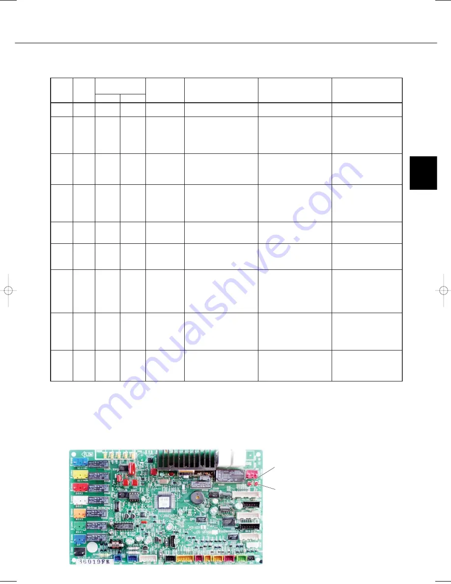
If an alarm occurs while the system is operating, the alarm display LED on the unit display will blink at 1-second
intervals (0.5 seconds ON, 0.5 seconds OFF) for the number of times that corresponds to the alarm code.
G
When facing the control PCB, the LED on the LD005 indicates the first digit, and the LED on the LD006
indicates the second digit.
For example, when alarm F10 occurs, the alarm code is 6A. Therefore, the LED for the first digit blinks 6 times,
then the LED for the second digit blinks 10 times.
LD006
Alarm display LED
LD005
07-032 VW-VF10BG_TD 2/15/07 11:24 AM Page 11
Summary of Contents for VW-VF10BG
Page 61: ......


