background image

ii

CAUTION

IMPORTANT INFORMATION

Do not place any containers that
contain liquid on top of the
system.

Doing so may result in system 
malfunction.

Prohibited

Be sure to securely reinstall all
components after cleaning.

Using the unit without the water tank, filter, or
other component securely installed 
may result in system malfunction. 

Req

u

ired

Install the system indoors, and
use in an environment between
5°C and 35°C.

In a particularly cold environment, the freeze-
prevention function may be 
activated, and the unit may not 
operate even when the power 
switch is turned ON.

Req

u

ired

Do not install in a location
exposed to dripping water.

Doing so may result in system malfunction.

Prohibited

Do not perform cleaning while the
system is operating.

Doing so may result in electric shock or
injury.

Prohibited

Grasp the power plug when
unplugging the power cord.

When unplugging the power cord, do not
grasp the cord. Instead, be sure to grasp the
power plug at the end of the cord 
and pull out the plug. Unplugging 
the cord incorrectly may result in 
electric shock, short circuit, or fire.

Req

u

ired

Do not use the system with the
filter removed.

Dust entering into the system may cause
system malfunction.

Req

u

ired

Avoid installation in high
locations. Install in a flat and
stable location.

Observe this precaution in order to ensure
that the system functions correctly. 
Failure to do so may result in the 
unit tipping over due to earthquake 
or contact by persons.

Req

u

ired

Do not obstruct the outlet.

Do not obstruct the air outlet with a curtain,
towel, or other item.
Doing so may result in system malfunction.

Prohibited

Do not place any items on the
unit.
Do not climb onto the unit.

Doing so may result in system 
malfunction, or in the unit tipping 
over.

Prohibited

Install in a location where there is
little humidity, oil mist, or other
airborne substance.

Select a location for use that is free of
humidity, dust, oil smoke (oil particles
generated from cooking), and salt. 
Failure to do so may result in 
odors or in system malfunction.

Req

u

ired

Secure space of 10 cm or more at
the left and right sides of the unit.

Also, allow servicing space of 100 cm or
more above and to the front of the unit.
Failure to do so may result in 
system malfunction.

Req

u

ired

Be sure to use normal tap
(drinking) water.

Never use water from a water purifier, water
from a water heater, alkali ion water, mineral
water, well water, seawater, or other types of
water. These types of water cannot be
electrolyzed and can cause the growth of
mold or bacteria, resulting in odor.

The electrolysis condition must
be set correctly according to the
water quality in the region where
the product is used.

For details, refer to “Setting the electrolysis
condition.”

Do not unplug the power cord,
even if the unit will not be used
for a while.

Even when the unit is stopped, cleaning
inside the system is performed automatically.
Check that there is water in the water tank,
and do not unplug the power cord.

Perform regular cleaning.

Follow the instructions under “Cleaning the
System,” in order to clean and maintain the
unit.
If the unit becomes especially dirty, mold may
grow, resulting in odor.

Do not direct the discharged air
directly onto walls or furniture.

Do not allow the discharged air to directly
contact walls or furniture.
It may damage the walls or furniture, resulting
in stains.

Be careful of freezing.

Freezing may result in system malfunction
and damage.

When relocating or storing the product (if it will
not be used for a long period of time), drain the
electrolyzed water and dry the air purification
element.

Req

u

ired

This system is not able to break down or remove
toxic gasses and substances.
Be sure to open a window or otherwise ventilate
the interior of the room if a release occurs.

If the system is used for a long period in a 
small room, open a window and ventilate 
the room as necessary.

Req

u

ired

07-032 VW-VF10BG_TD  2/15/07  11:24 AM  Page ii

Summary of Contents for VW-VF10BG

Page 1: ...m I Floor mounted model VW VF10BG 854 6 4849 256000 RoHS G This product does not contain any hazardous substances prohibited by the RoHS Directive WARNING G You are requested to use RoHS compliant parts for maintenance or repair G You are requested to use lead free solder REFERENCE No SM830156 ...

Page 2: ... may cause an insulation failure resulting in fire Required Do not apply water Do not immerse this unit in water or apply water to it Doing so may result in a short circuit and electric shock Do not wet Do not damage the power cord Do not scratch cut modify bend excessively pull on twist or otherwise damage the power cord Damage to the power cord may result in fire or electric shock Prohibited Do ...

Page 3: ...airborne substance Select a location for use that is free of humidity dust oil smoke oil particles generated from cooking and salt Failure to do so may result in odors or in system malfunction Required Secure space of 10 cm or more at the left and right sides of the unit Also allow servicing space of 100 cm or more above and to the front of the unit Failure to do so may result in system malfunctio...

Page 4: ...e Electrolyzed Water Concentration 3 2 2 Electrolyzed Water Concentration Measuring Tools 3 4 Section 4 Specifications 4 1 1 Product Specifications 4 2 2 Part Specifications 4 3 3 Control Specifications 4 3 4 Electric Wiring Diagram 4 4 Section 5 PCB and Functions 5 1 1 Explanation of Functions 5 2 2 Clearing the Total Times Filter Water Change Electrolyzing Unit Change 5 5 3 Turning the Buzzer ON...

Page 5: ...EATURES 1 System Features 1 2 1 Air cleaning using electrolyzed water 1 2 2 What is electrolyzed water 1 2 2 Name and Function of Parts 1 2 1 Space cleaning system 1 2 2 Unit built in control section 1 3 3 Unit front display 1 3 ...

Page 6: ...air however it is not a means of preventing or treating viral infections CAUTION The purified air is discharged after it has been purified by the electrolyzed water Indoor air is taken in Indoor air is taken in Indoor air is taken in The air passes through the Virus Washer element which is moistened with electrolyzed water Outlet Automatic louver This is used to adjust the air direction Control se...

Page 7: ... air in the room has been cleaned 5 times Indicator lamp status CHECK FILTER DRAIN ADDWATER SAVER OPERATION Meaning red red red red green green ON Unit is operating Blinking Unit is preparing for operation ON ON Reduced water usage is in effect ON ON Water must be added to the water tank ON Discard the water that has accumulated in the drainage tank Water drainage is in progress The DRAIN DRY lamp...

Page 8: ...product will not be used for an extended period of time 2 5 3 Draining 2 5 4 Odor 2 5 5 Adding salt 2 5 6 Maintenance 2 5 3 Using the System 2 6 4 Draining Procedure 2 7 5 Draining and Drying Procedure 2 8 6 Troubleshooting 2 9 1 Error notification 2 9 2 The following conditions are not malfunctions 2 9 7 Trouble Diagnosis 2 10 8 Cleaning the System 2 11 9 Storage when the system will not be used ...

Page 9: ...r G In regions where the electrolysis condition is 7 turn the electrolysis condition switch knob to 7 and add salt 1 g to the water tank Refer to Adding salt A pen or similar item is useful for turning the knob At the time of shipment this knob is set to 5 G When removing the front upper panel take care not to drop it and be careful when setting it on the floor 1 In regions where the chlorine ion ...

Page 10: ...t drips on the floor and can cause an accident if not wiped up 1 How to use the Water Filter packs G Remove the specified number of Water Filter packs from the plastic bag G Take off the water tank cap and put the specified number of packs into the empty tank G Fill the water tank with normal tap water G Replace the cap and return the water tank to its original position 2 Replacing Water Filter pa...

Page 11: ...me starts operation Approximately 3 minutes of preparation are required before the system begins operating While this preparation is in progress the fan remains stopped and no air is discharged from the system Be sure to use normal tap water G Never use water from a water purifier water from a water heater alkali ion water mineral water well water seawater or other similar types of water These typ...

Page 12: ...o dispose of the drainage tank water promptly 4 Odor If the water inside the system becomes fouled a strong chlorine smell may occur In this case drain and replace the water inside the system If the smell does not improve even after the water has been drained please contact the dealer 5 Adding salt Salt must be added in regions where the electrolysis condition is 7 When the DRAIN lamp lights add s...

Page 13: ... OPERATION lamp begins blinking and the system begins preparing for operation 3 minutes During this preparation the fan remains stopped and no air is discharged When preparation is complete the OPERATION lamp stops blinking and remains lit and operation starts If the system does not stop If the normal method fails to stop the unit pull out the power plug and contact the dealer where the system was...

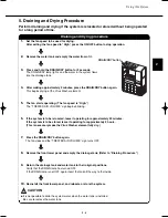
Page 14: ...ins level G Before removing the drainage tank verify that the system is stopped the OPERATION lamp is not lit 3 When draining the water do not open the tank lid Empty the tank through the rectangular hole at one end of the lid When all the water has been poured out place the drainage tank back in its original position 4 Insert the tank all the way into the unit Verify that the DRAIN lamp has turne...

Page 15: ...g The fan speed is High The TREATED AIR VOLUME sign begins blinking 6 If the system is to be relocated leave it operating for approximately 20 minutes If the system is to be stored leave it operating for approximately 2 hours This is necessary make the Virus Washer element fully dry 7 Press the DRAIN DRY button again The fan stops and the TREATED AIR VOLUME sign turns OFF 8 Remove the front lower ...

Page 16: ...ystem has operated for some time approximately one half day If the odor does not diminish change the electrolysis condition setting A bubbling sound can be heard This is the sound of water being supplied from the water tank This is not a malfunction Continue to use the system as is A humming sound can be heard This is the sound of the fan operating The fan will start when approximately 3 minutes h...

Page 17: ...nd check that there is no short circuit in the sensor Check that the humidity sensor is correctly connected to the control PCB and check that there is no short circuit in the sensor Check that the electrolysis unit water temperature sensor is correctly connected to the control PCB and check that there is no short circuit in the sensor Turn the power OFF and back ON and check whether alarm F29 occu...

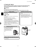
Page 18: ...ouring powder or similar substances and do not apply commercially available liquid insecticides or similar substances Doing so may result in deformation or discoloring In addition if using a chemical wipe follow the precautions for that product CAUTION Cleaning the unit when it is dirty G Wipe with a soft cloth that has been soaked in water G If the unit is particularly dirty use a soft cloth soak...

Page 19: ...all the high collection filter with the side where TO FACE FAN is printed facing toward the unit the fan G If the surface of the high collection filter is facing the wrong way air intake may be impeded resulting in lower air discharge and increased noise CAUTION G After cleaning the filters and returning them to their original positions press and hold the RESET button for 3 seconds The FILTER lamp...

Page 20: ...onnect the top of the front panel Press at the points marked PUSH at the top left and right of the front panel then pull the top of the panel toward you to remove it 2 Remove the 4 screws and remove the housing styrofoam The DRAIN DRY lamp turns OFF G Verify that the system is stopped 3 Remove the outlet filter case 1 Press inward to disengage the front tab 2 Pull downward 4 Remove the holding bra...

Page 21: ...ular maintenance contract is recommended Request new filters from the dealer where the system was purchased G Verify that the system is stopped 1 Remove the water tank 2 Pull out the scale filters 6 filters located on the bottom 3 Insert the new scale filters taking care that they are facing in the correct direction CAUTION This product is marked and conforms with relevant standards as it satisfie...

Page 22: ...3 1 3 Measuring The Water Sample CONTENTS 3 MEASURING THE WATER SAMPLE 1 Measuring the Electrolyzed Water Concentration 3 2 2 Electrolyzed Water Concentration Measuring Tools 3 4 ...

Page 23: ...perating 2 When the cleaning operation has finished use the syringe for the water sample and obtain 1 mL of water from the electrolyzed water tray Add the water into the container that is supplied with the residual chlorine concentration meter Add the water sample into the container supplied with the residual chlorine concentration meter Sampling the circulation water 3 Use the syringe for purifie...

Page 24: ...of 2 5 ppm 8 If the hypochlorous acid concentration is not within the designated range 2 5 ppm change the electrolysis condition according to the table below and replace the water in the electrolyzed water tray Then measure the concentration again I Judging the hypochlorous acid concentration Standard range over 2 5 ppm If the measured concentration is not within the standard range 2 5 ppm change ...

Page 25: ...idual chlorine concentration meter 3 Container for measuring the water sample concentration Container provided with the residual chlorine concentration meter 4 Container for dividing the purified water beaker approximately 50 mL 5 10 mL syringe for purified water used to dilute the concentration 6 1 mL syringe for the water sample 7 Purified water Approximately 500 mL of purified water is used to ...

Page 26: ...4 1 Specifications 4 CONTENTS 4 SPECIFICATIONS 1 Product Specifications 4 2 2 Part Specifications 4 3 3 Control Specifications 4 3 4 Electric Wiring Diagram 4 4 ...

Page 27: ...NW K11 VW white Munsell value N8 5 Side panels NW K12 VW gray Munsell value N4 0 Single phase 220 240 V 50 60 Hz Suitable floor space approximate m2 100 1 7 parallel plug with grounding contact Control section Display LED lamps Operating modes Service temp range Water used ON OFF FAN SPEED LOUVER FILTER RESET CHILD LOCK DRAIN DRY OPERATION HUMIDITY SAVER ADD WATER DRAIN FILTER CHECK TREATED AIR VO...

Page 28: ...ure C 20 30 40 50 60 0 2 1 3 4 6 5 7 8 Resistance kΩ Temperature C 2 Part Specifications G Fan motor coil resistance Model No DK8 63F280H Resistance Red White 26 6 Ω Ω White Blue 26 6 at 20 C Blue Red 26 6 Intake temperature sensor Electrolyzing unit water temperature sensor 3 Control Specifications Microcomputer control Settings Fan speed select HIGH MEDIUM LOW Service functions Alarm display G T...

Page 29: ... OFF before starting work Performing this work while the lamps are lit will result in electric shock SYMBOLS FM DRV2 RY001 005 009 Drain pump Float switch FLUSH Float switch 1 Relay TH1 THERMISTOR ROOM Temp THERMISTOR WATER Temp TH2 ELTD TRODE Electrode LM Louver motor HU Humidity sensor RE REACTOR CR VF10B Control PCB POW VF10BG Power PCB FAN VF10B Fan PCB IND PCB SW PCB Sub PCB Thermistor Connec...

Page 30: ...r PCB POW VF10BG 5 3 3 Fan PCB FAN VF10B 5 3 4 Display Section PCB IND VF10B 5 4 5 Control Section PCB SW VF10B 5 4 6 Electrolysis Condition Setting PCB SUB VF10B 5 4 2 Clearing the Total Times Filter Water Change Electrolyzing Unit Change 5 5 3 Turning the Buzzer ON OFF 5 6 4 Changing the Cleaning Monitor Display 5 7 ...

Page 31: ...k float switch plug CN013 Room temperature sensor plug CN012 Water temperature sensor plug CN011 Electrolysis setting plug CN042 Humidity sensor plug CN010 Fan motor signal I O plug CN009 RC plug CN041 Drain pump plug CN002 Drain valve plug 1 CN005 Drain valve plug 2 CN006 No 1 maintenance pin CN026 No 2 maintenance pin CN027 EEPROM memory IC IC007 The type of memory IC shown below may also be use...

Page 32: ...5 3 5 PCB and Functions 2 Power PCB POW VF10BG 3 Fan PCB FAN VF10B 250V AC 5A F201 AC IN CN201 Fan motor plug CN301 ...

Page 33: ...witch SW506 Louver switch SW503 Fan speed switch SW502 Operation ON OFF switch SW503 SW B plug CN502 SW D plug CN501 6 Electrolysis Condition Setting PCB SUB VF10B Electrolysis Condition Setting switch SW601 G At time of shipment Knob set to 5 G When setting the electrolysis condition refer to Electrolysis setting condition and the number of water filters NOTE ...

Page 34: ...completed 1 Clearing the total times for filter and water change Step 1 Short circuit maintenance pin 1 on the control PCB Step 2 Press the FILTER RESET button The buzzer sounds once and the total times are cleared 2 Clearing the total time for electrolyzing unit change Step 1 Short circuit maintenance pin 2 on the control PCB Step 2 Press the FILTER RESET button The buzzer sounds once and the tot...

Page 35: ...the RC plug on the PCB Note Connect the 3P of wire K to the RC plug on the Control PCB and connect the 2P of the wire K to the remote control unit If another wire has already been plugged into the remote control unit replace with wire K Regarding how to open the lid of the remote control unit refer to the Instruction Manual supplied with the remote control unit Procedure Press and hold the button ...

Page 36: ...ration for change and Procedure refer to 3 Turning the Buzzer ON OFF Cleaning monitor display 1 Setting data 00 Standard display setting at time of shipment from the factory Unit status Total airflow TREATED AIR VOLUME Stopped 0 Less than 300 m3 300 Less than 600 m3 Operating 600 Less than 900 m3 900 Less than 1200 m3 1200 Less than 1500 m3 1500 m3 or more 2 Setting data 01 Humidity indicator Disp...

Page 37: ...he electrolysis tank 6 5 3 Replacing the circulation pump 6 7 4 Replacing the float 6 8 5 Replacing the fan motor 6 9 6 Replacing the room temperature sensor 6 10 7 Replacing the humidity sensor 6 11 8 Cleaning the electrolyzed water tray 6 12 9 Cleaning the water receptacle 6 12 10 Replacing the solenoid valves 6 13 11 Replacing the PCBs inside the electrical component box 6 15 ...

Page 38: ...ture sensor High collection filter Pre filter Water tank Electrolysis tank Float switch Circulation pump 6 2 6 Maintenance Procedures Before beginning work stop the system and be sure to unplug the power cord from the outlet 1 Diagram of Functional Parts ...

Page 39: ...at the points marked PUSH at the top left and right of the front upper panel then pull the top of the panel toward you to remove it 1 Use a Phillips head screwdriver to remove the 4 screws then remove the housing styrofoam 2 G Verify that the system is stopped and the power cord has been unplugged CAUTION Remove the outlet filter case 1 Press inward and disengage the front tabs 2 Pull downward 3 R...

Page 40: ...the removed joint to the new Virus Washer element 7 G If the joint is not securely attached water leakage will occur CAUTION Install the Virus Washer element Follow the procedure for removal in the reverse order When attaching the tube to the joint insert the tube all the way until the end of the tube makes contact Pull on the tube and verify that it does not disconnect 8 Joint Stopper ...

Page 41: ...er cord Remove the top and bottom parts of the front panel Remove the water tank and remove divider panels A and B 4 screws each Remove the electrical component box cover 4 screws 4 3 2 1 Remove the 3 screws that fasten the top panel and the 16 screws that fasten the rear panel Then lift up the top panel 1 and pull the rear panel back in order to remove it 2 5 Disconnect the electrolysis tank cord...

Page 42: ...cket B Remove the top joint and left side joint from the electrolysis tank unit To remove the joint press the stopper at the base of each joint while pulling on it 7 Remove the screws 2 from electrolysis tank installation bracket A then disconnect it from electrolysis tank installation bracket B Remove the screw 1 that fastens the wiring installation band then pull out the water temperature sensor...

Page 43: ...e electrolysis tank Disconnect the circulation pump cord from the cord clip 2 5 1 1 Cut the binding bands 2 inside the electrical component box then open the cord clips 2 and disconnect the circulation pump connector 3 Remove the installation screws 2 from the circulation pump installation bracket then remove the circulation pump together with the bracket Remove the screws 3 from the circulation p...

Page 44: ...stallation bracket Float switch installation nut Float switch 4 Replacing the float Perform steps from Replacing the circulation pump Disconnect the drain float switch connector 2 2 1 1 Loosen the float switch installation nut on the float switch installation bracket then remove the float switch 3 ...

Page 45: ...over from the electrical component box 4 screws Remove the pre filter and high collection filter Remove installation brackets A B C and D 8 screws and remove the filters from them Press the tabs 2 on the left and right of the fan case cover toward the inside to disengage them 4 3 2 1 Cut the binding bands inside the electrical component box then disconnect the motor connectors 2 5 Insert a hex scr...

Page 46: ...crews 6 Replacing the room temperature sensor Perform steps from Replacing the fan motor Disconnect the room temperature sensor cord from the cord clip then cut the binding bands 2 inside the electrical component box and disconnect the room temperature sensor connector 2 3 1 1 Remove the sensor installation bracket 2 screws Disconnect the room temperature sensor cord from the cord clips 4 location...

Page 47: ...or Perform steps from Replacing the fan motor Disconnect the humidity sensor cord from the cord clip then cut the binding bands 2 inside the electrical component box and disconnect the humidity sensor connector 2 3 1 1 Remove the sensor installation bracket 2 screws Disconnect the humidity sensor cord from the cord clips 4 locations 3 Remove the screw 1 from the sensor cover then remove the sensor...

Page 48: ... Rinse the scale filters with water Plug the power cord and press the ON OFF button Press the DRAIN DRY button to drain the water to the drainage tank Empty the drainage tank 8 7 6 5 4 3 2 1 9 Cleaning the water receptacle Stop the system and unplug the power cord Remove the water tank then remove the scale filters Perform steps from Replacing the Virus Washer element Then remove the Virus Washer ...

Page 49: ...cord Remove the top and bottom parts of the front panel Remove the water tank Remove the divider panel A 4 screws then remove the electrolyzed water tray cover 2 screws and remove the electrical component box cover 4 screws 3 2 1 Remove the 3 screws that fasten the top panel and the 16 screws that fasten the rear panel Then lift up the top panel 1 and pull the rear panel back in order to remove it...

Page 50: ...l component box then disconnect the solenoid valve connector and remove the cord from the clamps 2 6 2 Remove the solenoid valve installation bracket A 2 screws then disconnect the transparent tube from the left joint Lift up the solenoid valve unit while pulling it out toward the front For the method used to disconnect the transparent tube from the joint refer to step from Replacing the Virus Was...

Page 51: ...he top and bottom parts of the front panel Remove the electrical component box cover 4 screws Disconnect all cords that run into the electrical component box Next remove the screws 2 each on the left and right sides that fasten the electrical component box and remove the electrical component box 3 2 1 The PCBs are arranged as shown in the figure below When removing the power PCB or fan PCB first r...

Page 52: ...7 1 7 Installation CONTENTS 7 INSTALLATION 1 Accessories 7 2 2 Installation Location 7 3 3 Installation Procedure 7 4 ...

Page 53: ...rt the power plug securely all the way to the base Do not use a plug that is not fully inserted or that is damaged Do not use a loose power outlet Doing so may result in electric shock or in fire caused by heating G Do not install outdoors or in any location where rainwater may contact the system Doing so may result in electric shock or fire G Rinse out the water tank every day and keep it clean T...

Page 54: ...tion may result in greater operating noise and the risk of tipping over If the unit tips over water will spill out 5 Be sure to connect the ground wire CAUTION Minimum 100 cm Minimum 10 cm Minimum 100 cm Minimum 10 cm 1ø AC 220 240 V 2 pin plug with grounding socket CAUTION Avoid installing in locations such as those listed below G Nearby windows and other locations that are susceptible to the eff...

Page 55: ... to the wall Plasterboard thin sheet or hollow wall Drive a plug for use in hollow walls into the wall Then use a screw to fasten the provided chain to the wall Use a plug that is correct for the thickness of the wall Mortar concrete wall Drive a plug for use in concrete into the wall Then use a screw to fasten the provided chain to the wall I Remove the front upper panel in order to clean the out...

Page 56: ... Manual 3 Tighten the cap At this time check that no water spills from the water tank 4 Place the water tank in the designated position in the unit 5 Insert the tank gently 6 Press the control panel ON OFF button 7 Verify that this product begins operating correctly At this time verify that there is no abnormal noise from the unit and that there is no vibrating noise Control section panel FILTER l...

Page 57: ...Miscellaneous 8 1 8 CONTENTS 8 MISCELLANEOUS 1 Maintenance of Virus Washer by Customer 8 2 2 Pack Test 8 3 ...

Page 58: ...removing the wet scale filters Remove the water tank then remove the scale filters on the bottom face The scale filters are connected by resin Wash the scale filters with water to wash off any scale Return the scale filters to their original location while taking care about the installation direction NOTE If dirt becomes noticeable replace the scale filters with new ones The general guide for repl...

Page 59: ...ens G Supplied package approx 4 ml for pack test of chlorine ions G Pack test for total hardness WAK TH Measuring Method 1 Pour in approx 4 ml of tap water until the mid line is reached in the test pack 2 Add the ion interchange water or distilled water to the test pack approx 4 ml adding to the tap water until the test pack is full Pay attention to not let the liquid overflow The test sample will...

Page 60: ... standard colors on the chart were determined using colors from standardized solutions Bromide ions iodide ions cyanide ions and phosphate ions react with the reagent inducing color changes Sulfite ions thio sulfate ions and sulfide ions can interfere with the color results These sulphur compounds can be oxidized with hydrogen peroxide Because of the high chloride concentration the Chloride Low Ra...

Page 61: ......

Reviews: