background image

– 3 –

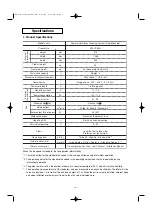
Model 

n

ame

Commercial 

S

pace Clea

n

i

ng


S

y

s

tem (Floor-Mo

un

ted)

Prod

u

ct No.

Hei

g

ht

Exter

n

al

dime

ns

io

ns

Electr

ical

char

acter

i

s

tic

s

Fa

n

Width

Depth

Prod

u

ct wei

g

ht

Operati

ng

 wei

g

ht

Water ta

n

k capacity

Exterior color (M

uns

ell 

nu

mber)

Power 

s

o

u

rce

Power cord le

ng

th

Operati

ng

 c

u

rre

n

t

Power co

nsu

mptio

n

Power factor

Model 

n

ame    Qty.

Rated airflow

Motor o

u

tp

u

t (No. of pole

s

)

Protective device

s

Operati

ng


S

W

S

ervice temperat

u

re

Operati

ng


n

oi

s

e

G

u

ide to water refill

Primary acce

ss

orie

s

mm

mm

mm

k

g

k

g

L

Filter

s

dB (A)

hr

s

/refill

°C

m

A

W

W

%

m

3

/mi

n

VW-VF

8

AG

615

1,0

8

5

2

3

0

40

44 (whe

n

 water ta

n

k i

s

 f

u

ll)

Approx. 4

S

ilky 

S

hade (1 Y

8

.5 / 0.5)

S

i

ng

le-pha

s

e,   220 – 240 V,   50 / 60 Hz

Protective thermo

s

tat, f

us

e

B

u

ilt-i

n


un

it co

n

trol 

s

ectio

n

Lo

ng

-life filter (i

n

take 

s

ide)

Protective 

n

et (o

u

tlet 

s

ide)

T

u

rbo: 45 / Hi

g

h: 

38

 / 

S

ta

n

dard: 

38


*2

T

u

rbo: Approx. 4 / Hi

g

h: Approx. 6 / 

S

ta

n

dard: Approx. 9 

*

3


Tip-over preve

n

tio

n

 chai

n

, U

s

er’

s

 Ma

nu

al, I

ns

tallatio

n

 Ma

nu

al

5 – 

3

0

S

irocco fa

n

    1

1.5 (No 

g

ro

un

d)

1.1 / 1.2

100 / 115

3

0 (4P)

91 / 96

T

u

rbo: 

8

 / Hi

g

h: 5 / 

S

ta

n

dard: 

3


*1

Specifications

1. Product Specifications

When the fan speed is standard, the fan operates intermittently.

*1: The rated airflow for the standard fan speed is the average airflow during intermittent operation.

*2: The operating noise for the standard fan speed is the operating noise when the fan is operating during

intermittent operation.

*3: The guide to water refill is the number of hours at a room temperature of 20°C and 35

%

 relative humidity.

*  The operating noise conforms to JIS standards, and was measured in an anechoic chamber. Therefore it is the

value at a position 1 m in front of the unit and a height of 1 m. When the unit is actually installed, ambient noise

and noise reflection ordinarily result in noise than the value indicated here.

06-289 Virus_Washer-TM  8/31/06  2:19 PM  Page 3

Summary of Contents for VW-VF8AG

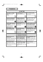
Page 1: ...r Do not soak this unit in water or apply water to it Doing so may result in a short circuit and electric shock Do not wet Do not damage the power cord Do not scratch cut modify bend excessively pull on twist or otherwise damage the power cord Damage to the power cord may result in fire or electric shock Prohibited Do not use chlorine based or acidic detergents when cleaning the water tank unit or...

Page 2: ...t in system malfunction or in the unit tipping over Prohibited Install in a location where there is little humidity cigarette smoke or other airborne substance Select a location for use which is free of humidity dust cigarette smoke incense smoke oil smoke oil particles generated by food preparation salt or ammonia Failure to do so may result in odors or in system malfunction Required Secure space...

Page 3: ...38 2 Turbo Approx 4 High Approx 6 Standard Approx 9 3 Tip over prevention chain User s Manual Installation Manual 5 30 Sirocco fan 1 1 5 No ground 1 1 1 2 100 115 30 4P 91 96 Turbo 8 High 5 Standard 3 1 Specifications 1 Product Specifications When the fan speed is standard the fan operates intermittently 1 The rated airflow for the standard fan speed is the average airflow during intermittent oper...

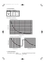
Page 4: ...tance kΩ Temperature C 2 Part Specifications G Fan motor coil resistance G Thermistor characteristics Model name KUE4T 31CPZ Blue Brown 29 91 Resistance Purple Blue 9 00 Ω Ω Yellow Purple 5 81 Yellow Pink 14 96 Intake temperature sensor Electrolyzing unit water temperature sensor 3 Control Specifications Microcomputer control Settings Fan speed select turbo high standard Service functions Alarm di...

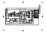
Page 5: ...ROOM THERMISTOR CS CONTROL SWITCH CR1 INDOOR CONTROLLER CR2 FILTER CONTROLLER POW POWER CONTROLLER IND IND LAMP ASSY TERMINAL PLATE CONNECTOR TERMINAL F1 F2 FUSE 2X 3X RY006 AUXILIARY RELAY ELEC TRODE ELECTRODE DESCRIPTION IND LAMP WTH RC TRANS S TRANS P TA DP FS2 IC Q 24VDEN TRANS S TRANS P IC Q 24VDEN FS2 DENKYOKU FS2 DF TH1 TH2 L N L N S R F2 1 1 7 1 2 1 3 6 5 4 3 2 1 1 2 1 2 1 2 1 3 1 3 1 3 1 ...

Reviews: