– 12 –
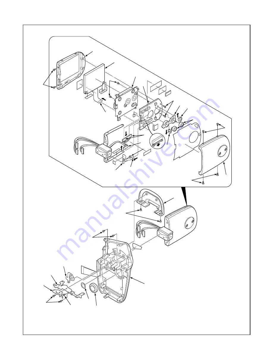
2-3. REMOVAL OF CABINET RIGHT, LCD AND VF1 BOARD
1. Two screws 1.7 x 4
2. Spring button
3. Button LCD
4. Two screws 1.7 x 2.5
5. Two screws 1.7 x 2
6. Assy cover joint base
7. Screw 1.7 x 2.5
8. Holder joint
9. Assy button power
10. Speaker, 8
11. Cabinet right
12. Four screws 1.4 x 3
13. Cover LCD back
14. Assy wire VF1 & SY1
15. Assy wire VF1 & CP1
16. FPC
17. Two screws 1.7 x 4
18. FPC
19. LCD
20. Two screws 1.7 x 2.5
21. Two connectors
22. Two microphones
23. Holder mic
24. VF1 board
25. Holder monitor
26. Two screws 1.4 x 3
27. Cover LCD front
28. Screw 1.4 x 2
29. Unit sw FPC
1
2
3
4
5
6
7
8
9
10
11
12
12
13
14
15
16
17
18
25
20
21
21
22
23
24
19
26
27
28
29


