197
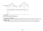
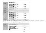
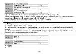
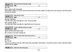
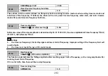
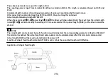
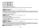
Fig. F9-7 Application of Stop at Fixed Length
In Fig.F9-7, the driver drives the motor, and the motor, in turn, drivers the spindle through the belt. The shaft that
contact with the spindle can measure the line speed of it which will be transmit to the drive by the sensor in the form of
pulse. The driver will calculate the length based on the number of pulses it received. When the actual length.≥ preset
length, the driver will give stop command automatically to stop the spinning.
FA Protection Parameter
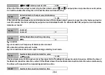
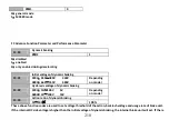
FA.00
Motor overload protection
0
~
2
1
0
:
disabled
Without overload protection
(
use with caution
)。
1
:
common motor
(
thermal relay, low speed compensation
)
Since cooling conditions of common motor deteriorates at low speed, the motors thermal protection threshold should
also be adjusted. The “low speed” here refers to the operating frequency lower than 30Hz, with which the motor will be
lowered of the overload protection threshold.
2
:
variable frequency motor
(
thermal relay, without low speed compensation
)
The cooling effect of variable frequency motor is not affected by the motors speed, so low speed compensation is not
necessary.
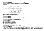
FA.01
Motor overload protection factor
20.0
%~
120.0
%
100.0%
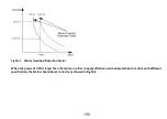
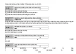
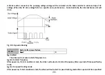
In order to apply effective overload protection to different kinds of motors, the motor overload protection factor should
be correctly set to limit the Max.output current of the driver. The factor is the percentage of motor rated current to the
rated output current of the driver.
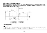
When the motor’s power level matches the driver, the protection factor can be set to 100%, as showed in Fig. FA-1.

