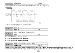
203
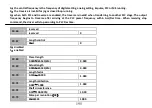
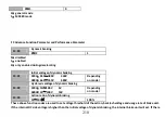
0.0
~
30.0s
10.0
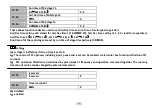
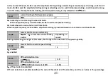
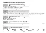
This parameter defines the delay time from the time when the output current of VFD is higher than the overload
pre-alarm level (FA.12) to the time when overload pre-alarm signal is sent.
Notice
:
With the setting of parameter FA.12 and FA.13, when the output current of the driver is higher than overload pre-alarm
level (FA.12), the driver will send pre-alarm signal after delay time (FA.13), i.e. the control panel will display “A-09”.
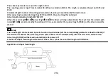
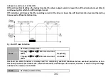
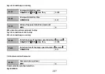
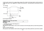
FA.14
Temperature detection threshold
0.0
℃~
90.0
℃
65.0
℃
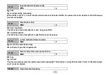
For details see function description NO.51 of F7.18
~
F7.21.
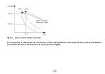
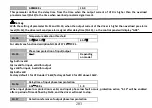
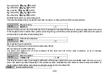
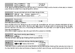
FA.15
Phase loss protection of input/output
0
~
3
Depending
on model
0
:
both invalid
1
:
invalid for input, valid for output
2
:
valid for input, invalid for output
3
:
both valid
Factory default 1 for VFD under 7.5kW, factory default 3 for VFD above 11kW.
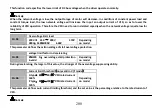
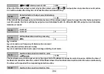
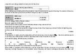
FA.16
Delay time of input phase loss protection
0.0s
~
30.0s
1.0
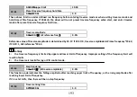
When input phase loss protection is valid, and input phase loss fault occurs, protection action “E-12” will be enabled
after a period of time defined by FA.16, and the driver will coast to stop.
FA.17
Detection reference of output phase loss protection


