User Manual & Datasheet V 2.1
1
Introduction
2
Operating Principle
CAPVEL is composed of specially developed capaci-
tance change gauging circuit. It uses fast RISC based
processor to perform all the complicated jobs of evaluat-
ing the level out of the capacitance. This capacitance is
formed by the sense rod and the metallic container wall,
where containers are non-metallic or non-uniformly wide
or having turbulent fluid, a metallic stilling well is pro-
vided. The amount of capacitance is proportional to the
level of material between the sense rod and metallic wall
of stilling tube or container.
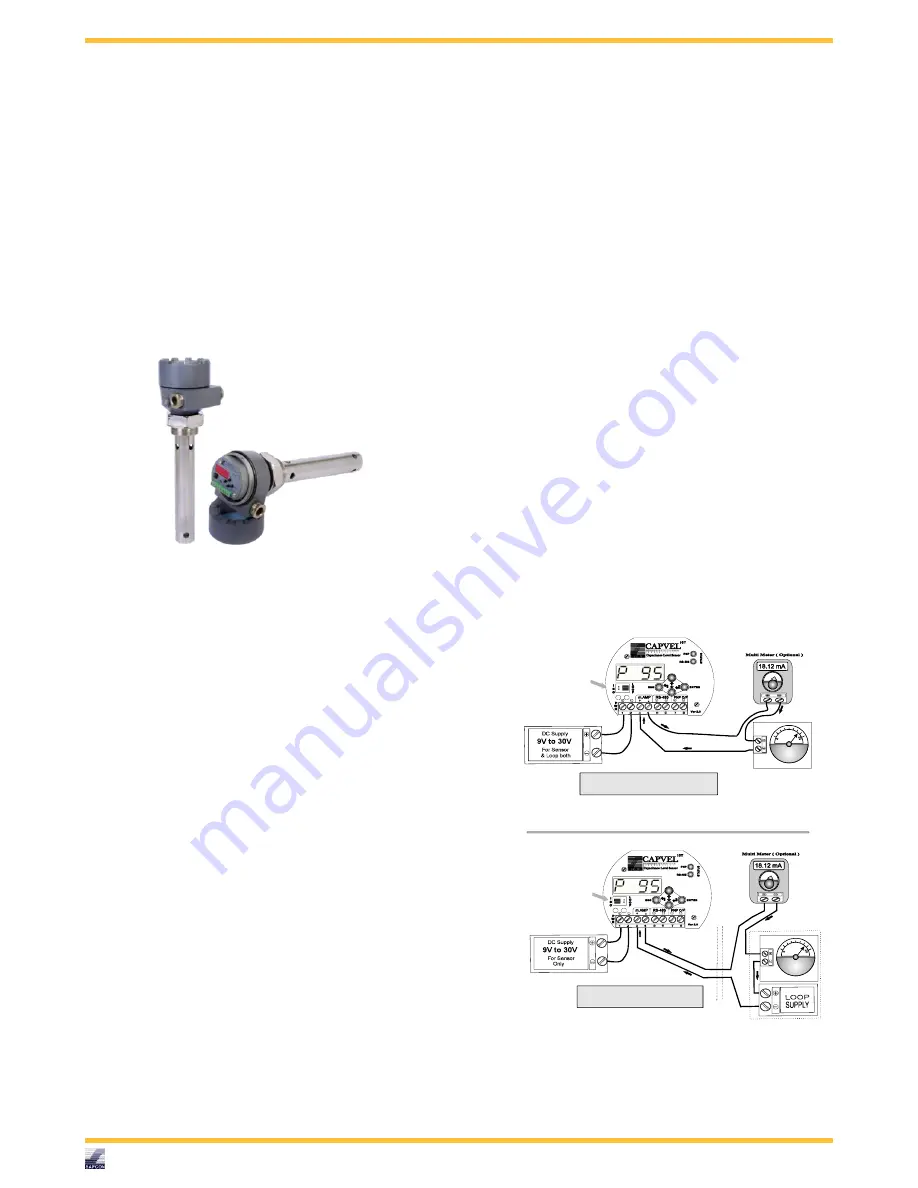
Figure 1: Capvel
3
System Description
CAPVEL is composed of cast aluminium housing,
supplied with suitable mounting arrangement viz.NPT,
BSP or Flanges and two metallic cable entries.
An
external Earthing / Grounding terminal is also provided.
The sensing rod which is mostly Teflon coated. This
sensing rod can be replaced by flexible probe for some
applications.
The stilling tube is also provided for
turbulent fluids, irregular width tanks, non-metallic
tanks or for fluids with low dielectric (e.g. diesel).
Opening the threaded aluminium cover, an electronic
insert could be found. This is the electronic unit which
converts the level into 4-20 mA signal depending on the
calibration. The status LED is a bi-color LED that blinks
alternately in Red and Green to indicate instrument is in
process of converting the level to 4-20 mA signal. Two
DIP switches are provided to calibrate the 4 mA and
20 mA points. The calibration is easy and a complete
procedure is given in "Calibration" page. The two wires
connected at the back are pre-connected sensor wires
and should not be disturbed. Also while calibration try
to keep hands away from the wires of terminal 6 and 7.
Now referring to the "Connection Diagram", Capvel can
be wired in two possible combinations. Preferred one
is galvanically isolated, 4-wire combination where only
one source of power is available, 3-wire, non-isolated
combination can also be used. The converted level signal
can be sensed using a 4-20 mA indicator or PLC 4-20
mA input or multimeter in 40 mA range or any-other
device that takes 4-20 mA signal as input.
4
Features
5
Applications
6
Capvel-BT Features
•
User Interface : 2 DIP sw 2 LED
•
Output-1 : 4-20 mA, Galvanically Isolated
•
Output-2 : Rs-485 Digital Data
7
Capvel-ICT Features
•
User Interface : 4 Digit Display with 4 Keys + 2
LED
•
Output-1 : 4-20 mA, Galvanically Isolated
•
Output-2 : Rs-485 Digital Data
•
Output-3 : Controlling Devices connected with Ex-
ternal Relay
3-wire Single Supply Operation
mAmp
Maximum Internal Resistance of Indicator/PLC/Scanner
[(Sensor Supply - 4V) x 50] Ohm
Indicator or
Scanner
or PLC
4-20mA
mAmp
Maximum Internal Resistance of Indicator/PLC/Scanner
[(Loop S upply - 4V) x 50] Ohm
Indicator or
Scanner
or PLC
4-20mA
4-wire Dual Supply Operation ( Galvanic Isolated )
J umpers
( Towards ISO )
J umpers
( Towards LOOP )
I
S
O
L
A
T
I
O
N
Figure 2: Connection Diagram
Sapcon Instruments Pvt.Ltd.
R
5


