background image

The Sapling Company, Inc.
1633 Republic Road
Huntingdon Valley, PA 19006

215.322.6063 P.
215.322.8498 F.
www.sapling-inc.com

7

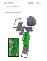
Plastic Surface (Wall) Mount Installation

Mount Housing to Wall and/or Gang Box - 

To mount the housing to the wall, drive two (2) plastic anchors into the wall (not 

supplied in kit) and take two pan head screws (also not supplied in kit) and drive them into the plastic inserts leaving an 1/8th inch 

gap between the head of the screw and the wall. Mount the housing to the wall by lining up the two holes in the back of the top of 

the housing with the two screws with the 1/8 inch gap from the wall and slide the housing onto the heads of the screws. To mount the 

housing to the gang box, take the four (4) 6-32 x 1” screws (supplied in kit) and screw them through the four holes in the center of the 

inside of the housing and the four holes in the gang box.


Note: If using a metal gang box, a ground must be provided to the gang box.

Feed Wiring Into the Housing - 

Take the wire coming from the inside of the gang box and feed it through the hole in the middle of 

the housing.

Plug and Secure Wiring - 

Loosen the provided wire clamp (comes attached to the inside of the housing) and slip excess wiring 

through and tighten the clamp. After securing excess wiring, plug the jack at the end of the wiring into the appropriate jack on the back 

of the display board.

Mount Display Board to Housing - 

 Using the four (4) self tapping, 6-19 x 1/2” flat head screws supplied in the assembly kit, take 

the display board and screw it to the front side of the clock housing (4 screws per clock).

Snap on Filter - 

Take the red filter bezel and snap it on to the front side of the housing.

Snap on Frame - 

Take the gray frame and snap it on to the front side of the housing.

Installation Instructions

Summary of Contents for SBD 1000 Series

Page 1: ...SBD 1000 Series Wired Clock The Sapling Company Inc 1633 Republic Road Huntingdon Valley PA 19006 215 322 6063 P 215 322 8498 F www sapling inc com Installation Manual V6...

Page 2: ...10 SBD 1000 Series Wired Clock Table of Contents 2 Flush Mount Installation 3 Surface Wall Mount Installation 4 Metal Double Mount Installation 5 Plastic Surface Wall Mount Installation 6 Plastic Sur...

Page 3: ...d in the kit 3 Disconnect the red filter from the display panel 4 Connect the wiring as shown on the wiring diagram 5 IMPORTANT If using a low voltage system 24 volt make sure that the transformer is...

Page 4: ...d machine screw nut included in the kit 3 Disconnect the red filter from the display panel 4 Connect the wiring as shown on the wiring diagram 5 IMPORTANT If using a low voltage system 24 volt make su...

Page 5: ...r mounting rod 7 Insert the support bracket onto the hanger mounting rod 8 Screw the two 2 nuts included in the kit onto hanger mounting rod and secure the clock base to wall 9 Connect the ground wire...

Page 6: ...The Sapling Company Inc 1633 Republic Road Huntingdon Valley PA 19006 215 322 6063 P 215 322 8498 F www sapling inc com 6 Plastic Surface Wall Mount Installation e w q r t y Installation Instructions...

Page 7: ...n the center of the inside of the housing and the four holes in the gang box Note If using a metal gang box a ground must be provided to the gang box w Feed Wiring Into the Housing Take the wire comin...

Page 8: ...e Sapling Company Inc 1633 Republic Road Huntingdon Valley PA 19006 215 322 6063 P 215 322 8498 F www sapling inc com 8 Installation Instructions Plastic Double Mount Installation q t i a y r w w e u...
Page 9: ...f the three holes on the mounting pole where the wiring will be routed the installer will chose which hole at the end of the pole to use based on how far they want the clock to sit from the wall Screw...

Page 10: ...ons between the wiring harness and the switch box wires using wire nuts Perform this task for both clocks If using IP clocks wiring will not be supplied with the clocks the installer will be responsib...

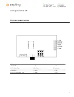
Page 11: ...ey PA 19006 215 322 6063 P 215 322 8498 F www sapling inc com 11 Wiring Information Wiring and Jumper Settings Jumper Number On Off JP1 12 24 Hour Mode 12 Hour Mode 24 Hour Mode JP2 Brightness Brighte...

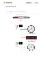
Page 12: ...com 12 Wiring Information 2 Wire Digital Communication Wiring Information SMA 2000 or 3000 Series Master Clock SAM Series 24V Wired Clock SBD 1000 Series Wired Clock SAM Series 24V Wired Clock 18 19 1...

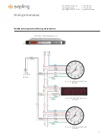
Page 13: ...ww sapling inc com 13 Wiring Information RS485 Communication Wiring Information SMA 2000 or 3000 Series Master Clock 24V or 110V SRM Series RS485 Clock 24V or 110V SBD 1000 Series Clock 24V or 110V SR...

Page 14: ...odel c Make sure the ground wire is not touching other wires NOTE If you fail to follow instructions a and b listed above the fuses can be blown The clock is not receiving an input signal What do I do...

Page 15: ...un on the same communication line using a RS485 protocol What is the maximum distance between clocks on the communication line Each SBD 1000 digital clock has a RS485 input and an output Each output p...

Page 16: ...tion between the equipment and receiver 3 Connect the equipment into an outlet on a circuit different from that to which the receiver is connected 4 Consult the dealer or an experienced radio TV techn...

Reviews: