


31
The Sapling Company, Inc.
670 Louis Drive
Warminster, PA 18974
USA
P. (+1) 215.322.6063
F. (+1) 215.322.8498
www.sapling-inc.com
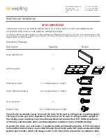
Elapsed Timer Control Panel Installation - Optional Accessory
3.3V, 100MA
3.3V, 100MA
Timer RX
Temp RX
Common
Timer TX
Temp TX
Not Used
Not Used
Input B+
Output A-
Output B+
Rly1 NO .5A 120vac/24vdc
Rly2 NO .5A 120vac/24vdc
User 1 Input
User 2 Input
User 3 Input
User 4 Input
Common
5V, 40MA
9 -12V, 40MA
Dukane Pulse
Dukane Reset
24Vac Sync
120Vac Sync
AC/DC Com
AUX
5V Dry Cont
(-) Neutral
(+) Line
Earth
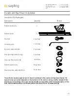
1
1
1
1
1
J4
J5
J7
J10
J11
J9
RS485
Common
Input A-
5
5
4
8
10
24 VAC/DC
110/220 VAC
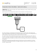
Reminder:
Electricity can be dangerous at higher voltages. Keep the electricity to this device turned off
until after the wiring has been added. Do not add new circuitry while the device is operating.
CAT5 Cable Notes:
Use an 8 conductor 24AWG CAT5 cable up to 100 feet long, and use the wire colors shown above. Pin 1, Pin 2,
Pin 3, and Pin 4 each use the wire pair described above. Both of the green 5-pin connectors should be wired the
same way: a wire going into port 1 on one connector should also go into port 1 on the other connector.
Strip the insulation back 1/4 inch on all wires and twist the two wires of each pair together. Insert each pair
of wires into the appropriate port on the connector and tighten the screws.
*Customer must supply CAT5 cable to connect the Elapsed Timer to the digital clock.
CAT5 Cable up to 100ft (33.3m) long
Pin 5 - Should be left empty.
Pin 4 - Blue & Blue/White
Pin 3 - Green & Green/White
Pin 2 - Orange & Orange/White
Pin 1- Brown & Brown/White
5
4
3
2
1
J4