background image

33

The Sapling Company, Inc.
670 Louis Drive
Warminster, PA 18974
USA

P. (+1) 215.322.6063 
F. (+1) 215.322.8498
www.sapling-inc.com

Buzzer - Optional Accessory

To activate the buzzer with a countdown,

 log on to the web interface and perform the following 

actions:

1. Click on the “Input and Relay Settings” button, followed by the “End Countdown” button. Find the 

drop-down menu next to “On Countdown complete, close” and select “Relay 2”

2. In “for ____ seconds” set the amount of time that you wish the buzzer to sound when the 

countdown ends. The number must be a whole number from 1 to 60.

3. Press the Submit button.

To activate the buzzer without a countdown,

 click on the Input and Relay Settings button, followed 

by either the Elapsed Timer or Inputs button. For the button or input that you wish to trigger the buzzer, 

set the Action as Relay 2. Press the submit button after inputting these settings.
Pressing the button on the Elapsed Timer Control Panel or activating the input will cause the Relay to 

toggle to the opposite of its current setting and remain that way until the button or input is activated 

again. If the Buzzer is currently off, this will turn the buzzer on. If the buzzer is currently on, this will turn 

the buzzer off.

(

IMPORTANT: 

Detach clock from power source before installing new circuitry. DO NOT add new circuitry 

while the clock is operating)

The Buzzer accessory kit (

L-BUZZ-3300-1

)


comes with all wires already installed in the correct 

ports for the J10 and J11 connectors, and installation can be completed by attaching these 
connectors to the J10 and J11 sockets on the clock main board.


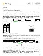
If you wish to set up the buzzer on existing connectors, use the instructions below.

You will need the buzzer, the small yellow 26AWG wire, a wire stripper, and an eyeglass 
screwdriver.

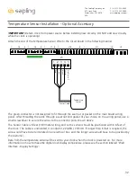
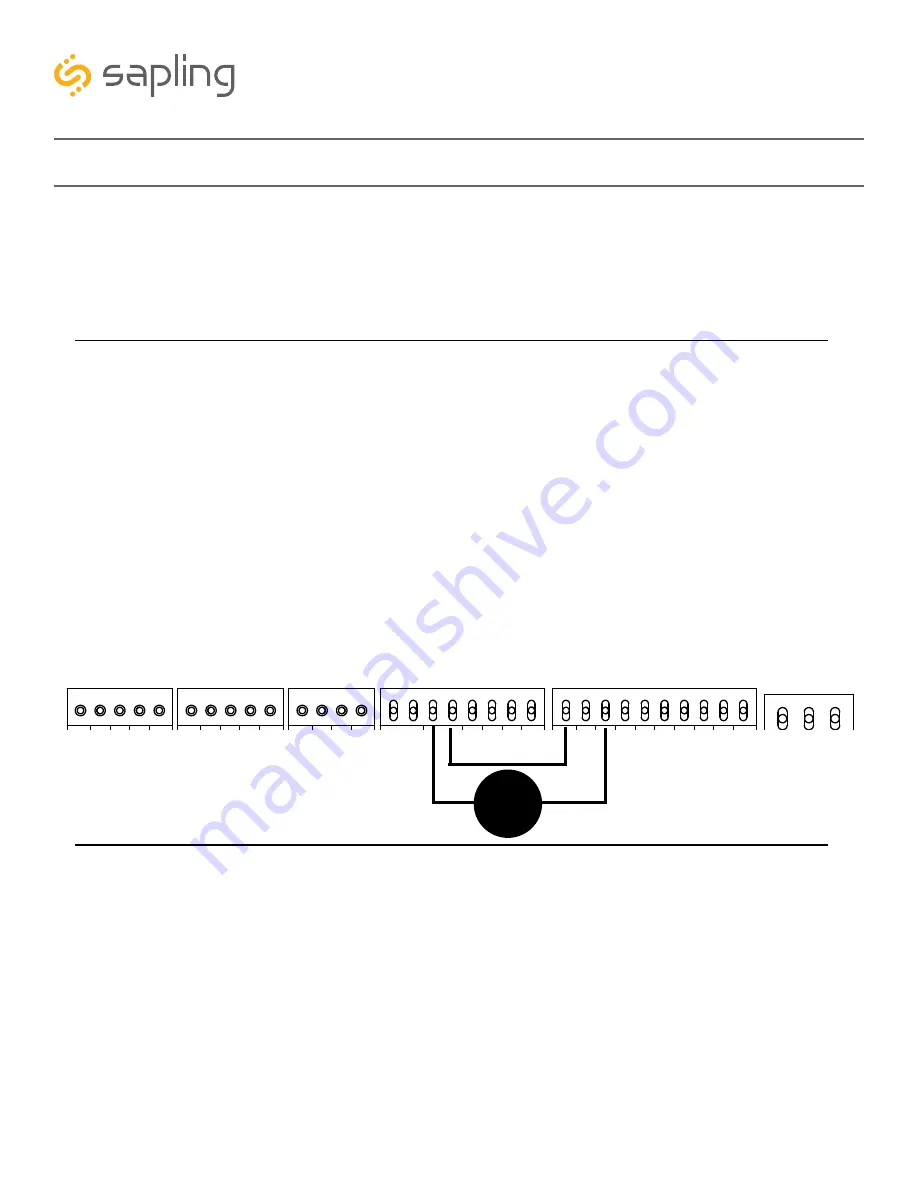
1) Use the eyeglass screwdriver to open connector ports J10-3, J10-4, J11-1, and J11-3. Refer to the diagram 
below for the position of each port.
2) Connect the red wire on the buzzer to port J11-3.
3) Connect the black wire on the buzzer to port J10-3 (relay 2) on the main board.
4) Strip the ends of the extra yellow wire and use it to connect J10-4 (relay 2) to J11-1.
5) Use the eyeglass screwdriver to close all four ports. Tug gently on each wire to confirm  that each wire 
end is secure.

3.3V, 100MA

3.3V, 100MA

Timer RX

Temp RX

Common

Timer TX

Temp TX

Not Used

Not Used

Input B+

Output A-

Output B+

Rly1 NO .5A 120vac/24vdc

Rly2 NO .5A 120vac/24vdc

User 1 Input

User 2 Input

User 3 Input

User 4 Input

Common

5V, 40MA

9 -12V, 40MA

Dukane Pulse

Dukane Reset

24Vac Sync

120Vac Sync

AC/DC Com

AUX

5V Dry Cont

100-240vac         L1

100-240vac         L2

Ground

1

1

1

1

1

J4

J5

J7

J10

J11

J9

RS485

Common

Input A-

5

5

4

8

10

Black

Red

3

4

1

3

Yellow

Buzzer

Summary of Contents for SLD Premium Series

Page 1: ...The Sapling Company Inc 670 Louis Drive Warminster PA 18974 USA P 1 215 322 6063 F 1 215 322 8498 www sapling inc com Installation Manual V2 1 SLD Premium Large Digital Clock Current as of April 2019...

Page 2: ...Menu 48 49 Error Messages 50 Web Interface Log In 51 Home Page 51 Network Settings 52 53 Enterprise Settings 54 General Settings 55 Time Settings 56 Daylight Saving Time 57 Servers 58 Display Setting...

Page 3: ...t and will not sway or move as you stand on it Take precautions to avoid injury by potential safety hazards near the point of installation including but not limited to heavy machinery sharp objects ho...

Page 4: ...Digits 0604 6 15 2cm Four 0606 6 15 2cm Six 0904 9 22 9cm Four 0906 9 22 9cm Six 1204 12 30 5cm Four 1206 12 30 5cm Six Clocks with 4 or 2 5 digits are NOT Large Digital Clocks For power source inform...

Page 5: ...e subnet as the clocks A web browser such as Internet Explorer Microsoft Edge or Mozilla Firefox An internal or external Wi Fi network card A wireless router or wireless access point for the LAN that...

Page 6: ...clock supports it A means of keeping a record of the clock serial numbers locations and IP addresses Create a table like the one shown below Preparing to Install Network Requirements PoE Wired LAN To...

Page 7: ...word DIRECT will appear on the display for a few seconds On a 4 digit clock only the letters DIRE will appear In this mode a clock will wait four minutes for the user to access it before automaticall...

Page 8: ...atible with 802 11n Check your router settings for more information Be aware of walls or other obstructions made of thick concrete or sheet metal as these may block the signal entirely Logging into th...

Page 9: ...Fi network Network passwords must be twenty six characters or fewer 9 If you wish to set a static IP address change DHCP Auto On from ON to OFF then enter information for the Static IP address Subnet...

Page 10: ...click on the Log Out button 14 Connect your computer to the clock s new network then log in to the clock again and confirm that the clock is accessible on the network You should be able to access the...

Page 11: ...fy the following conditions Has an RJ45 Port Has either a Red or Amber display Has either 6 0 or 9 0 digits Part number ends with 0 If any of these conditions are not met PoE cannot be used with the c...

Page 12: ...or each You may also configure them later When finished click on the Log Out button 10 Log in to the clock again and confirm that the clock is accessible on the network You should be able to access th...

Page 13: ...for wired synchronization systems and Elapsed Timer if your system uses these Refer to the appropriate section of this manual for each 7 Test and confirm all features are working properly as it will...

Page 14: ...he network using a LAN cable Obtaining the configuration file 1 DO NOT Start wifiDirectLoader exe First set up one clock using the steps described in the System Setup section of this manual 2 Once you...

Page 15: ...ect the configuration file that you downloaded from the first clock If you cannot see the file confirm that the Files of Type field is set to Large Digital WiFi ldwifi 2 Under the Options menu select...

Page 16: ...ky and should be placed in a location where the signal is not interfered with or blocked Be aware of large structures made of stone concrete bricks or sheet metal as these materials will block a GPS s...

Page 17: ...ION OF THIS MANUAL FOR INSTRUCTIONS All network and or master clock equipment must be powered and configured before you install the clock If the network and or master clock equipment is not properly i...

Page 18: ...or Yellow orange wires for 21 5 26 5 volts AC DC in the 24 volt model If you are using the 24 volt model make sure that the wiring leading to the clock is from an ISOLATED transformer To power your cl...

Page 19: ...o open the wiring panel Store the screws in a safe place 8 Unscrew the seal nuts that cover the gasket sizes that most closely resemble the diameter of your power cable If you are also installing comm...

Page 20: ...onto the wiring panel 9 Pass all power and communication cables through the seal nut followed by the gasket on the wiring panel Wall Mount Installation Common Temp TX Not Used Input B Output A Output...

Page 21: ...a better position then tighten the securing nut again Repeat until you are able to slide the clock onto the mounting pieces 15 Use a Phillips screwdriver to insert and tighten the securing screws thro...

Page 22: ...IS MANUAL FOR INSTRUCTIONS All network and or master clock equipment must be powered and configured before you install the clock If the network and or master clock equipment is not properly installed...

Page 23: ...g mount only Mounting plate screw Mounting plate washer 8X5 16 Quantity 1 1 2 per base 1 per base 2 per base 2 per base 1per base 16 per base 16 per base Picture You will also need enough screws to mo...

Page 24: ...on a section of drywall all marked holes should overlap a wall stud 4 Use a drill to drill the holes into the wall When finished install the wall anchors if needed for your application CHECK YOUR WIR...

Page 25: ...uble and Flag Mount Installation 5 Slide the pole into the mounting base 6 Secure the pole to the mounting base using the two pole bolts lock washers and grounding wire 7 Attach the securing plates to...

Page 26: ...tion for your clock type 26 The Sapling Company Inc 670 Louis Drive Warminster PA 18974 USA P 1 215 322 6063 F 1 215 322 8498 www sapling inc com Double and Flag Mount Installation 6 and 9 Wall Mount...

Page 27: ...n the sides of the pole Look at the position of the wiring panel on the back of your clocks for help determining which hole is appropriate for your wires Connect the grounding wire in the pole to the...

Page 28: ...d earlier If not please take the clock down and do so now For information on wiring refer to the sections of this manual labeled Inputs and Outputs Common Temp TX Not Used Input B Output A Output B Rl...

Page 29: ...Mount Installation 19 Use the Phillips screwdriver to close the wiring panel 18 Screw the seal nuts back onto the wiring panel 20 Slide the clock onto the mounting pieces Slide the clock onto the moun...

Page 30: ...n tighten the securing nut again Repeat until you are able to slide the clock onto the mounting pieces 22 Use a Phillips screwdriver to insert and tighten the securing screws through the mounting piec...

Page 31: ...evice turned off until after the wiring has been added Do not add new circuitry while the device is operating CAT5 Cable Notes Use an 8 conductor 24AWG CAT5 cable up to 100 feet long and use the wire...

Page 32: ...d within 6 feet of the clock The cable is unshielded 4 conductor 22AWG 33mm If longer than 6 feet is required the wire would have to be terminated in an electrical box and the longer wire would have t...

Page 33: ...wer source before installing new circuitry DO NOT add new circuitry while the clock is operating The Buzzer accessory kit L BUZZ 3300 1 comes with all wires already installed in the correct ports for...

Page 34: ...24 VAC Sync Dukane Pulse 5V Dry Contact AC DC Common 5V 40MA Dukane Reset Output A Rly1 NO 5A 120vac 24vdc Rly2 NO 5A 120vac 24vdc User 1 Input User 2 Input User 3 Input User 4 Input Common 5V 40MA 9...

Page 35: ...10VAC Interface or 240VAC Interface 24VAC Interface Inputs Sync Wire 59 Minute Correction 58 Minute Corrections 1 4 Dry Contact Closure 110VAC Interface or 240VAC Interface 24VAC Interface 10 9 110VAC...

Page 36: ...6063 F 1 215 322 8498 www sapling inc com Inputs Sync Wire Input Output National Time Rauland Rauland Digital 10 2 Dig Line 5V Dry Contact Closure 110VAC Interface or 240VAC Interface 24VAC Interface...

Page 37: ...Common 5V 40MA 9 12V 40MA Dukane Pulse Dukane Reset 24Vac Sync 120Vac Sync AC DC Com AUX 5V Dry Cont Neutral Line Earth 1 1 1 1 1 J4 J5 J7 J10 J11 J9 RS485 Common Input A 5 5 4 8 10 24 VAC DC 110 220...

Page 38: ...uts Output A Output B Rly1 NO 5A 120vac 24vdc Rly2 NO 5A 120vac 24vdc User 1 Input User 2 Input User 3 Input User 4 Input Common 5V 40MA 9 12V 40MA Dukane Pulse Dukane Reset 24Vac Sync 120Vac Sync AC...

Page 39: ...12V 40MA Dukane Pulse Dukane Reset 24Vac Sync 120Vac Sync AC DC Com AUX 5V Dry Cont Neutral Line Earth 1 1 1 1 1 J4 J5 J7 J10 J11 J9 RS485 Common Input A 5 5 4 8 10 24 VAC DC 110 220 VAC 1 2 3 4 RS48...

Page 40: ...P device s that the user previously marked as priority will be the only clocks shown in the program window 4 Device Count This number is the amount of IP devices that are displayed on the Network Moni...

Page 41: ...sage before sending it The message will repeat ten times once sent c Send to Selected Clocks Applies the message to whichever clocks have been highlighted on the Device List d Send to All Digital Cloc...

Page 42: ...of this manual labeled Network Monitor Software Quick Access Menu Pressing this button will cause the Download Configuration window to appear a Enter Password The default password is 6063 b Select Co...

Page 43: ...e Send Countdown to Digital Clocks button Applies only to Digital Clocks Find Hands Commands Analog Clocks to resynchronize their hands The user will be prompted to enter a password to authenticate th...

Page 44: ...s Group 1 in the drop down menu B Clocks buttons Clicking on a Clocks button will display each of the group s devices in the box to the right C Device Box Displays the devices for the selected group T...

Page 45: ...Network Repeaters Wi Fi Analog Wi Fi Digital IP Analog and or IP Digital clocks When the box next to the clock type is checked the user will be able to view that clock type on the Monitor Screen Filte...

Page 46: ...Applies only to battery powered analog clocks This option is not available with the CFL version of the monitor Configure Email Alerts By selecting this option the user is able to choose which email a...

Page 47: ...e to File When clicked allows the user to save the all of the information in the Network Monitor device list as a CSV file which can be printed from Microsoft Excel If the monitor is showing devices f...

Page 48: ...Clocks Performs the same action as the Send Countdown to Digital Clocks button 6 Send Looping Message to Clocks Performs a similar action to the Send Message to Digital clocks but allows the user to s...

Page 49: ...g this option the user can copy the settings from an IP device and save them to whichever computer is running the Network Monitor Your computer will automatically prompt you for the location of the sa...

Page 50: ...clock are black this means that the clock is working normally The CFA and CFL versions of the Monitor cannot run at the same time If managing Wi Fi clocks and IP clocks at the same time use the CFA N...

Page 51: ...al Settings Takes the user to the General Settings page General Settings includes settings for Time Configuration Daylight Saving Time NTP Servers and Login Settings 3 Diagnostics Takes the user to th...

Page 52: ...lue was selected in the Select Network field 6 Network Password This field allows the user to connect the clock to a wireless network by entering the network password Network passwords must be 25 char...

Page 53: ...itors Broadcasts the clock s presence to all instances of Network Monitor Software running on the network 14 Send Specific Monitor IP When set to ON broadcasts the clock s presence to an instance of t...

Page 54: ...pplies any changes to the previous options when pressed THIS SECTION IS REQUIRED ONLY IF YOUR NETWORK USES WPA2 ENTERPRISE ENCRYPTION WPA2 PSK NETWORKS DO NOT REQUIRE USE OF THESE SETTINGS IF YOUR WI...

Page 55: ...locks 3 Servers Wi Fi Wired LAN Sync Only Takes the user to the Servers page Not used with wired and standard wireless clocks 4 Display Settings Takes the user to the Display Settings page 5 Login Set...

Page 56: ...ng Kong is an offset of 8 The clock may be configured to function as part of a Zone Clock through this option 5 Bias Seconds This setting allows the user to alter how much faster or slower the IP cloc...

Page 57: ...Daylight Saving Time Once the date month and time are set click Submit to apply the settings to the clock Example March 1st at 2 00 By Country This mode allows the user to select preset Daylight Savi...

Page 58: ...ry other servers if the selected server fails When checked the clock will rotate through the listed addresses each time the clock performs a synchronization check 3 Network Sync Every Allows the user...

Page 59: ...ill display the time for the number of seconds entered in the box After the selected amount of time passes the clock will change to show Date or Temperature If a time of 0 is selected the clock will n...

Page 60: ...t font for the numbers on the display Enter a number from 0 through 3 to choose one of four character sets 9 Blink Colon After If the clock does not receive new time data in the entered time span minu...

Page 61: ...age The default Technician password is 6063 Administrator Allows the user to view and change any setting in the clock Web Interface including the passwords on the Login Settings page The default Admin...

Page 62: ...umber of minutes that pass between each time that the clock powers its transmitter to get NTP data 10 Worst Server Wi Fi and Wired LAN only Lists the number of the NTP server that has responded the le...

Page 63: ...ed clocks 2 Force Restart Restarts the clock Performs the same software function as disconnecting the clock from power then reconnecting it 3 Restore Default settings When clicked this button causes t...

Page 64: ...an input is activated 3 Outputs Takes the user to the Outputs page This page controls signals outputted by the clock relays 4 End Countdown Takes the user to the End Countdown page This page controls...

Page 65: ...lapsed Timer control panel through this page For detailed instructions on the many functions and uses of the Elapsed Timer refer to the Elapsed Timer Manual Web Interface Elapsed Timer 65 The Sapling...

Page 66: ...nting down from a time specified by the user in the Seconds box Reset Activating the input restarts whichever countdown count up is in progress Start Stop Activating the input causes the timer to paus...

Page 67: ...panel LED settings The lights are green while the timer is running and red when the timer has been paused Code Blue 1 When an input programmed with Code Blue is activated for the first time the count...

Page 68: ...1 Refer to the next page for output options 3 Relay 2 Output Allows the user to select which time protocol will be sent by the clock through Relay 2 Refer to the next page for output options 4 Submit...

Page 69: ...nds off 58th Minute 4 The clock performs an hourly correction that takes 55 seconds and occurs between XX 59 05 and XX 59 00 It also performs two daily corrections one at 5 00AM and one at 5 00PM Each...

Page 70: ...re than 60 seconds B A user can select what the clock will do after reaching at the end of a countdown by selecting the circle next to either Time or Count Up If Time is selected the clock will displa...

Page 71: ...he file it only selects the file 3 Update Web Pages From File Takes whichever file was selected with the Choose File button and applies the update file to the clock 4 Update Firmware From Sapling Upda...

Page 72: ...ivated the clock will switch to 00 00 00 or 00 00 on a 4 digit clock and the count up will begin Pressing SW2 again will start or resume count up if the count up is not running or pause the count up i...

Page 73: ...te PM or disappear to indicate AM When the display is set to the 24 hour format the full 24 hour time will appear on the display no other lights should appear Some examples 5 30 AM 12 hour format 5 30...

Page 74: ...he clock should get the signal within five minutes Once the clock has been synchronized it will attempt to acquire a time signal once every minute Whether or not a clock actually receives a signal is...

Page 75: ...ne If you have an in house NTP server confirm that the NTP server has been set as a time source and that the server is distributing the correct time I configured my IP clock through the Wi Fi connecti...

Page 76: ...ppear on the monitor 2 Confirm that the viewing filters on the Network Monitor are set to display Wi Fi Clocks 3 Confirm that you have the latest version of the Network Monitor software as older versi...

Page 77: ...e Sapling Company Inc To Goods which are altered modified or repaired in any place other than a Sapling Company Inc factory or by persons not expressly authorized or approved in writing by The Sapling...

Page 78: ...oes cause harmful interference to radio or television reception which can be determined by turning the equipment off and on the user is encouraged to try to correct the interference by one or more of...

Reviews: