SECTION 4
PART#
49-057 REV K
SAPPHIRE SCIENTIFIC RAGE
®
31
8. GENERAL SERVICE
ADJUSTMENTS
!
DO NOT
attempt to service this unit while it is
running. High speed parts as well as high
temperature components may result in severe
injury, severed limbs, or fatality.
ENGINE SPEED
1. To adjust the engine RPM, refer to the Engine
Operation and Service Manual for specific
instructions.
!
DO NOT attempt to adjust without a tachometer
and NEVER adjust the engine above 3200 RPM.
VACUUM RELIEF VALVE
With the unit running at full RPM, block off the
airflow at the vacuum inlet port and read the
vacuum gauge. If adjustment is required, shut the
unit down and adjust the locking nut tension on
the vacuum relief valve. Re-start the unit and
read the vacuum gauge. Repeat this process until
the vacuum relief valve opens at 13” Hg. Always
ensure the lock nut is retightened.
WATER PUMP DRIVE BELT
To tighten the water pump belt:
1. Loosen the four nuts, which hold the water
pump base to the frame.
2. Adjust the position of the belt tensioning.
3. While checking the alignment, tighten the nuts
that hold the water pump to the base.
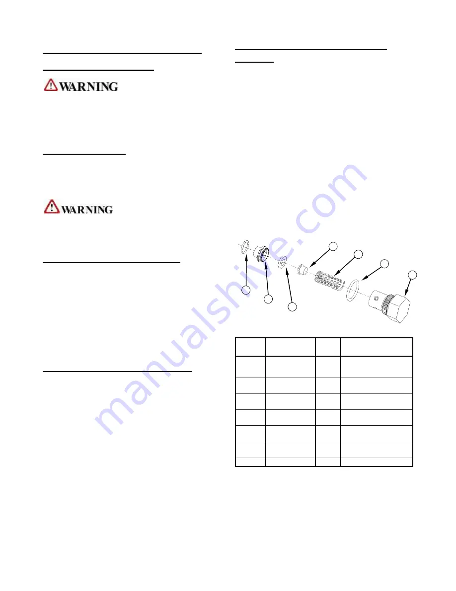
SOLUTION OUTLET CHECK
VALVE
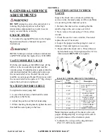
Inspect the check valve whenever performing
service on the chemical pump or if flow problems
are occurring in the chemical system.
1. Remove the check valve, ensuring that the
small o-ring on the seat comes out with it
2. Next, remove the seat using a 5/16 in. Allen
wrench
3. Check the seat for wear or debris. Clean and
replace the seat if necessary.
4. Inspect the poppet and the spring for wear or
damage. Clean and replace as necessary.
5.
Re-assemble the check valve. Thread the seat
by hand until snug. Then tighten with a 5/16 in
Allen wrench.
DO NOT
over-tighten.
23-063 VLV, CHECK, CHECK VLV MANIFOLD
Item #
Part
Number
Qty.
Description
1
27-009
1
CAP, CHECK VALVE
ASSY. SS
2
41-007
1
ORING, 7/8 ID X 1-
1/16 OD
3
15-007
1
SPRING, CHECK
VALVE ASSY.
4
27-010
1
POPPET, CHECK
VALVE ASSY
5
27-004
1
INSERT, SEAT-CHK
VLV ASSY TM
6
27-011
1
SEAT, CHECK
VALVE ASSY.
7
41-008
1
ORING, ½ ID 5/8 OD
Note:
Improper seating of the check valve seat,
poppet, damaged spring or o-rings will result in
poor performance of the chemical system.
6. Lubricate the o-rings with o-ring lubricant.
(Part # 13-003) and re-install.
7
6
5
4
3
2
1
Summary of Contents for rage
Page 1: ...Service and Operation Manual 2604 Liberator Dr Prescott AZ 86301 1 928 445 3030...
Page 16: ...SECTION 2 PART 49 057 REV K SAPPHIRE SCIENTIFIC RAGE 12 DIMENSIONAL DIAGRAM REAR MOUNT TANK...
Page 17: ......
Page 46: ...SECTION 5 PART 49 057 REV K SAPPHIRE SCIENTIFIC RAGE 40 CONSOLE ASSEMBLY DETAIL 1...
Page 47: ...SECTION PART 49 057 REV K SAPPHIRE SCIENTIFIC RAGE 41 CONSOLE ASSEMBLY DETAIL 2...
Page 48: ...SECTION 5 PART 49 057 REV K SAPPHIRE SCIENTIFIC RAGE 42...
Page 49: ...SECTION PART 49 057 REV K SAPPHIRE SCIENTIFIC RAGE 43 69 544 ASSY BEZEL AND PANEL 1 16...
Page 50: ...SECTION 5 PART 49 057 REV K SAPPHIRE SCIENTIFIC RAGE 44 69 445 ASSY BEZEL AND PANEL 17 25...
Page 51: ...SECTION 5 PART 49 057 REV K SAPPHIRE SCIENTIFIC RAGE 45...
Page 52: ...SECTION 5 PART 49 057 REV K SAPPHIRE SCIENTIFIC RAGE 46 69 710 VACUUM PUMP ASSEMBLY...
Page 53: ...SECTION 5 PART 49 057 REV K SAPPHIRE SCIENTIFIC RAGE 47 69 432 ASSEMBLY VACUUM RELIEF...
Page 57: ...SECTION 5 PART 49 057 REV K SAPPHIRE SCIENTIFIC RAGE 51 69 260 MANIFOLD BLOCK ASSEMBLY...
Page 63: ...SECTION 5 PART 49 057 REV K SAPPHIRE SCIENTIFIC RAGE 57 ELECTRICAL DIAGRAM...
Page 64: ...SECTION 5 PART 49 057 REV K SAPPHIRE SCIENTIFIC RAGE 58 HOSE IDENTIFICATION FLOW DIAGRAM...


