Apply to Viewing Size Range 136''(16:9) to 240''(4:3) of Smartmove series Motorized Screen
P1=P
P1>P
P1<P
17
5
250
180
35
15
5
10.5
Pd = P - 80
3
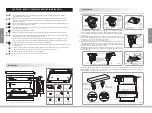
Instruction Manual for Ceiling Installation Parts
Thank you for purchasing a
product.
Before using, please read instructions carefully. After installation, store instructions for future reference.
Sapphire
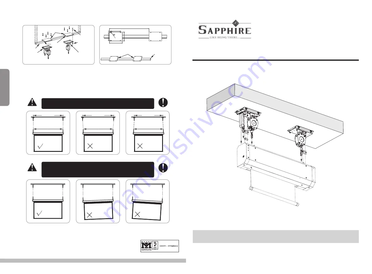
7. If the ceiling where you install the parts is not a flat Concrete Ceiling, then extra a mounting rack is necessary, Figure 8-9.
Iron Plate
(250x175x8mm)
Iron Square
Tube Beam
Left side Ceiling
Installation Part
M10x80mm
Screw
Iron Plate
weld tight
with Iron
Square
Tube Beam
Right side Ceiling
Installation Part
Flat Washer
Spring Washer
Screw Nut
Figure 8
Figure 9
Iron Plate weld tight with
Iron Square Tube Beam
The minimum cross section
of Iron Square Tube Beam
is 60x40x2mm
8. Please ensure all parts are mounted security before install screen.
9. For Skyshow screen installation pls refer to 'Instruction Manual for Smartmove series Motorized Screen.
10. Adjust screen to flat level, recheck the hanging distance to ensure straps are plumbness.
11. Connect and fix the power cable and network cable.
DISTANCE P1 MUST BE EXACTLY THE SAME AS P,
OTHERWISE IT MIGHT CAUSE PRODUCT FUNCTIONAL FAIL OR DAMAGE.
P1
P
Wrong Installation
P1
P
P1
P
Wrong Installation
AFTER INSTALLATION, DO NOT CONNECT ELECTRIC POWER UNTIL ENSURE THE WHOLE SCREEN
IS AT THE SAME HORIZONTAL LINE AND FIXED STICKERS OF THE SCREEN BOTTOM BAR HAS
BEEN REMOVED. OTHERWISE IT MIGHT CAUSE PRODUCT FUNCTIONAL FAIL OR DAMAGE.
Correct Installation
Correct Installation
Screen Flat
Wrong Installation
Screen lean
to the left
Wrong Installation
Screen lean
to the left
Warning
Constraint
Warning
Constraint
Techical
Assistance
If you need help with installing this screen please visit
www.sapphireav.com


