background image

Page:4


1

.

GENERAL INFORMATION

1

.

 About  Your  Locking  System


The S&G A-Series with Display

TM 

Electronic Lock has the following hardware components:


Lock 

 There are four different lock models available for the A-Series with Display

TM 

Platform.  These models 

include the 3006 (Pivot Bolt), 3007 (Direct Drive), 3028 (Motor Driven, Dead Latching), and 3029 (Motor Driven, 
Push / Pull).  The lock is housed within the container.


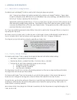
Digital Platform (DP) Keypad (31KP Series) 

 The 12-key alphanumeric  keypad on the front of the container used to 

enter PIN codes and programming commands.   The keypad will contain three LEDs (red, green, yellow), a beeper


to indicate the different states of the lock, and a display module.  The keypad also contains a USB connector that 
will allow a flash drive to be connected.


The * key is used with Programming Command Codes. It may also be used to clear the keypad if there is an input error 
by entering the * key twice.


Each time you press a number, letter, or other character on the keypad, it beeps and the 

keypad’s

 red LED flashes. If 

there is no beep or flash, check the batteries and try again (See section 2.10 

 Changing  the Batteries).


The # key acts as an enter function and must be used after each code entry.


The lock responds with different beep sequences to indicate 

different conditions. The beeps are indicated in the examples


by the symbol 

Q

. For example, five beeps are indicated by 

QQQQQ

.  You should always wait for each set of beeps to end 

before entering another number or letter, or you will


interrupt the lock’s instructions.


1

.

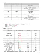
 Factory  Default  Settings


The A-Series with Display

TM 

Lock is shipped from Sargent & Greenleaf with factory default settings:


Bank Mode 

 enabled (Service Mode disabled)

Multiple User Mode 

 enabled (Time Delay 

 0 minutes; Duress 

 disabled)

Positions 00, 02, and 10 have default PIN Codes set at the factory:

1.

Programmer Code (00) - 00123456

2.

Manager Code (02) - 02020202

3.

User Code (10) - 10101010

The Programmer Code (PC) can only set up the operating parameters of the lock and download the audit trail data

.


The Programmer Code cannot open the container.


The A-Series with Display

TM 

Lock has the capacity for up to 30 PIN Code positions: 1 Programmer, 3 Managers, 6


Supervisors  who manage the lock programs, and up to 20 Users. PIN Codes 01-29 can open the lock.


To open the lock, use the factory setting for PIN position 10 with PIN Code 10101010. Enter 10101010# and the lock 
should open.  (If the lock does not open and beep patterns were heard after pressing the # key, check section 2.3 

“Beep

 Patterns

 to identify condition.)


We recommend that Users change their PIN Codes immediately after the PIN positions are assigned (Changing a PIN 
Code 

 Section 3.10).


Summary of Contents for 3006-2 Series

Page 1: ...y a qualified technician Anytime the keypad is removed from its mounting base either disconnect the lock cable or support the keypad so that it does not hang by the cable This could adversely affect the cable connector or the keypad receptacle Each time a button is pressed and the lock accepts the input it will emit a beep the red LED on the keypad will flash momentarily and a will be displayed on...

Page 2: ... Command 00 Enable Disable Manual Secure Mode 10 3 2 Command 03 Set Daylight Savings Time Time Change 10 3 3 Command 04 Set Daylight Savings Time Start Date 11 3 4 Command 05 Set Daylight Savings Time End Date 11 3 5 Command 06 Verify Daylight Savings Mode Settings 12 3 6 Command 10 Enable Daylight Savings Time 12 3 7 Command 11 Set Date 12 3 8 Command 12 Set Time 13 3 9 Command 13 Start the Clock...

Page 3: ... 30 Command 78 Set Time 26 3 31 Command 79 Identify Firmware Version 26 3 32 Command 82 Verify the iButton Touch Key Service Mode 27 3 33 Command 83 Disabling the Time Delay Override Feature 27 3 34 Command 90 Display Lock Serial Number 28 3 35 Command 96 Check Battery Level 28 3 36 Command 97 Display Time Date 28 4 SERVICE MODE OPERATION 28 4 1 Service Mode Initialization Single and Multiple 28 4...

Page 4: ...ifferent beep sequences to indicate different conditions The beeps are indicated in the examples by the symbol Q For example five beeps are indicated by QQQQQ You should always wait for each set of beeps to end before entering another number or letter or you will interrupt the lock s instructions 1 2 Factory Default Settings The A Series with DisplayTM Lock is shipped from Sargent Greenleaf with f...

Page 5: ... in day mode o Day Night mode 2 Any valid code Supervisor Manager or User can open the lock in day mode The lock cannot be opened in night mode 2 2 PIN Positions and Access Responsibilities Bank Mode This section defines each PIN position and the respective User functions as summarized in Tables A B PIN position 00 the Programmer position can only configure the lock and download the audit trail Th...

Page 6: ... Color Duration Normal Condition Each Keystroke 1 beep1 1 cycle Low Battery Warning 2 beep1 Red 5 cycles Low Battery Lockout 20 beep1 Red 1 cycle Start Time Delay 3 quick beep1 Red 1 cycle Time Delay Countdown 1 beep1 Red Every 10 seconds Time Delay Expired 10 quick beep1 Green 1 cycle Opening Window Countdown 2 beep1 Green Every 10 seconds Bolt Extension 1 beep2 1 beep1 Red 1 cycle Code Input Loc...

Page 7: ...If you make a mistake while entering a User Code press twice at any time to clear the lock and start over If you hear a brap after entering the key you have made an error Press key twice to clear and try again or you can wait 10 seconds and the lock will clear itself 2 6 Penalty Time Bank Mode Service Mode If you enter 5 incorrect codes in a row the lock goes into a 10 minute penalty time and cann...

Page 8: ...ps under each battery to release the battery Insert the new batteries into the compartment and move the spring clips back into place Please note that the polarity of the battery is designated on the inside of the compartment Press the keypad housing firmly back onto the base 2 11 iButton Touch Key The iButton touch key allows you to transfer the audit trail from the lock to your computer The audit...

Page 9: ...le disable duress 4 2 Identify the type of lock 4 3 Identify the lock mechanics 4 4 Identify the operating mode 4 5 Initialize the lock into service mode 4 6 Setup time delay override TDO type 4 7 Setup time delay value 4 8 Setup opening window value 5 4 Initialize the lock into service mode 5 5 Enable disable lock manager employee mode 5 6 Manager employee mode type 5 7 Manager employee mode open...

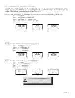
Page 10: ...n DST is enabled To setup the DST time change perform the following steps Step 1 Enter 0 3 Step 2 Enter 8 digit Programmer PIN Code 00 Step 3 Enter Time in HH format always 2 digits Step 4 Enter Time in HH format always 2 digits DST Change Time Enter Code Enter Time HH Confirm Time HH Example To set the DST change time to 2 AM using the factory default Codes Step 1 Enter 0 3 Step 2 Enter 0 0 1 2 3...

Page 11: ... Sunday Saturday The range for the Month setting is 1 12 January December To set the end date perform the following steps Step 1 Enter 0 5 Step 2 Enter 8 digit Programmer Step 3 Enter Week Day Month Step 4 Enter Week Day Month DST End Day Enter Code Enter Day WK DD MM Confirm Day WK DD MM Example To set the end day to the First Sunday in November Step 1 Enter 0 5 Step 2 Enter 0 0 1 2 3 4 5 6 Step ...

Page 12: ...T features using the factory default Codes Step 1 Enter 1 0 Step 2 Enter 0 0 1 2 3 4 5 6 Step 3 Enter 1 Step 4 Enter 1 DST ON Off Enter Code ENABLE DST 1 ON 0 OFF 1 CONFIRM DST 1 ON 0 OFF 1 3 7 Command 11 Set Date You must set the date to use Service Mode or audit trail functions The date should be entered in DDMMYY format where DD day MM month and YY year The Date should be set before initializin...

Page 13: ... MM Example To set the time as 1 42 PM use 13 42 using the factory default Codes Step 1 Enter 1 2 Step 2 Enter 0 0 1 2 3 4 5 6 Step 3 Enter 1 3 4 2 Step 4 Enter 1 3 4 2 Set Time Enter Code Enter Time HH MM 13 42 Confirm Time HH MM 13 42 The time date must be set and the clock started 13 before the settings are saved by the lock 3 9 Command 13 Start the Clock After setting the time and date values ...

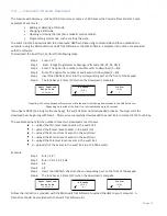
Page 14: ...it PIN Code Step 3 Enter New 8 digit PIN Code Step 4 Enter New 8 digit PIN Code again Change Code Enter Code Enter New Code Confirm New Code Example To change the default PIN code of 0 2 0 2 0 2 0 2 to 2 1 2 1 2 1 2 1 Step 1 Enter 2 2 Step 2 0 2 0 2 0 2 0 2 Step 3 2 1 2 1 2 1 2 1 Step 4 2 1 2 1 2 1 2 1 Change Code Enter Code Enter New Code Confirm New Code Example To change the default PIN code of...

Page 15: ... keypad will remain on while the audit trail is being downloaded to the USB flash drive Depending on the size of the Audit Trail this could take up to 45 seconds If you hear a BRAP one long continuous beep the audit trail was not downloaded properly You must start the download over beginning with Step 1 After you ve successfully downloaded the audit trail it is stored in the Touch Key The availabl...

Page 16: ...Step 2 Enter 8 digit Programmer Code Step 3 Enter 3 Function Number Step 4 Enter 3 Function Number Set Lock Mode Enter Code Enter New Mode 3 Confirm New Mode 3 The lock is now set in Dual Control mode requiring two valid opening PIN codes to gain access Once the lock has been put into dual control it will require a manager code and any other valid code to change operating modes Enable Multiple Use...

Page 17: ...Enter 5 Function Number Step 4 Enter 5 Function Number Set Lock Mode Enter Code Enter New Mode 5 Confirm New Mode 5 The lock is now set in Day Night Mode 1 This setting requires two valid opening PIN codes to open the lock in night mode and one valid opening PIN code to open the lock in day mode and enabled Enable Day Night Mode 2 For Day Night Mode 2 the customer can setup the lock so that there ...

Page 18: ... 2 1 Enter New Code Confirm New Code Change Code Enter Code Enter New Code Confirm New Code With the above example the default PIN code of 0 2 0 2 0 2 0 2 has been changed to 2 1 2 1 2 1 2 1 Example Step 1 Enter 3 3 Step 2 1 0 1 0 1 0 1 0 Step 3 2 0 1 5 2 0 1 5 Step 4 2 0 1 5 2 0 1 5 Change Code Enter Code Enter New Code Confirm New Code With the above example the default PIN code of 1 0 1 0 1 0 1...

Page 19: ...Enter Code Enter New Mode Number 2 Confirm New Mode Number 2 The lock can now send a duress signal through the interface module Disabling the Duress Alarm Feature The duress feature can be disabled without disconnecting the Duress Alarm Module by performing the following steps Step 1 Enter 3 8 Step 2 Enter 8 digit Programmer PIN code 00 Step 3 Enter 0 Step 4 Enter 0 OPTION 1 disable OPTION 2 enabl...

Page 20: ...eeps Dual control mode 4 beeps Multiple user mode 3 18 Command 45 Initializing the Lock Multiple User Mode Dual User Mode Manager Employee User Mode The lock can be initialized into Service Mode using command 45 and a properly programmed management touch key Please see Section 4 1 Initializing the Lock for more information on initializing the lock 3 19 Command 46 Setting Up the Time Delay Override...

Page 21: ...mand 47 Setting up the Time Delay The A Series with DisplayTM Lock can be programmed with a time delay feature Time delay applies only to those users who can open the lock The time delay can be set from 0 to 99 minutes If the lock is in the time delay period the red LED light on the keypad flashes and a single beep sounds every 10 seconds When the time delay expires the lock emits 10 rapid beeps t...

Page 22: ... 4 5 6 Step 3 Enter 1 0 Step 4 Enter 1 0 Time Delay Enter Code Enter Time Delay 0 99 10 Confirm Time Delay 0 99 10 To eliminate the time delay period enter 0 for the time delay minutes 3 21 Command 48 Setting Up the Opening Window If the time delay has already been set enter a User Code to start the time delay When the time delay expires the lock emits 10 rapid beeps and the opening window has beg...

Page 23: ...e lock is disabled this function will enable the lock If the lock is disabled this function will enable the lock Step 1 Enter 5 5 Step 2 Enter 8 digit Manager or Supervisor PIN code 01 09 NOTE Four high beeps indicate the lock is now enabled and 2 low beeps indicate the lock is now disabled Step 1 Enter 5 5 Step 2 Enter 0 2 0 2 0 2 0 2 3 24 Command 56 Enable Disable User Disable Feature Manager Em...

Page 24: ...0 1 2 3 4 5 6 Step 3 Enter 1 Step 4 Enter 1 The Manager Supervisor now has the ability to open the lock in Manager Employee mode 3 26 Command 73 Set Date You must set the date in order to use the Service Mode functions or the audit trail functions The date should be entered in DDMMYY format where DD day MM month and YY year The Date should be set when the lock is first set up and prepared for use ...

Page 25: ...w user code of 21212121 has been added to position 20 Command 75 Adding Code Positions Dual User Mode To add a user position perform the following steps Step 1 Enter 7 5 Step 2 Enter 8 digit Manager PIN Code 01 02 or 03 Step 2 Enter 8 digit Valid Secondary PIN Code 01 29 Step 3 Enter New 2 digit PIN position Step 4 Enter New 8 digit PIN Code Step 5 Enter New 8 digit PIN Code Add Code Enter Code Ad...

Page 26: ... this position To manage the PIN User Codes the PIN Code Position Verification Worksheet located on page 33 is recommended Step 1 Enter 7 7 Step 2 Enter PIN position to be verified and One long beep means no Code is set for that position One short beep means a Code is set Identify PIN Enter Code Please note that the lock will remain in this function until the key is pressed or if there are 10 seco...

Page 27: ...ectly Step 1 Insert the user or management touch key into the touch key reader Step 2 Enter 8 2 The lock will show a message on the display indicating that the touch key is valid or an error message indicating a problem with the touch key 3 33 Command 83 Disabling the Time Delay Override Feature If you do not want the Time Delay Override TDO function available it can be permanently disabled and al...

Page 28: ...de is being used to whoever is performing initialization at the lock The management touch key is used in conjunction with a keypad command to initialize the lock Lock initialization can only be completed after the date and time are set using the procedures outlined previously in this document If initialization is attempted before time and date are set the lock will sound two sets of 2 long beeps b...

Page 29: ...e keypad extension Step 2 Input the User or Manager four digit PIN code and press the key Step 3 Input the eight digit operation code supplied by the Lock Management System software and press the key The lock will illuminate the yellow LED and show the iButton icon on the display to acknowledge the Service Mode request and will then process the requested operation If the operation is verified and ...

Page 30: ...s as follows Step 1 Insert the Manager or User touch key into the touch key reader Step 2 Input the Manager or User four digit PIN code and press the key Step 3 Input the Manager or User eight digit PIN code supplied by the LMS software and press the key Step 4 The yellow LED and iButton icon will turn on during processing of code Step 5 After successful completion the lock s green LED will flash ...

Page 31: ...codes or bank user PIN codes This code will not open the lock 4 3 5 Revoke Dispatcher This is a management operation code that transfers the identity of a subcontractor system to the lock s table to prevent the subcontractor from performing any subsequent operations at the lock This code will not open the lock Reinstating the revoked dispatcher requires an Add Dispatcher command 4 3 6 Add Dispatch...

Page 32: ...Step 3 Input the Manager eight digit PIN code supplied by the LMS software and press the key Step 4 The yellow LED and iButton icon turn on during processing of code Step 5 At successful completion the lock s green LED will flash and emit three beeps Step 6 User inputs new time on keypad in HHmm format and presses the key Step 7 The lock s green LED will flash and emit three beeps Step 8 User inpu...

Page 33: ... 00 Programmer 01 Manager 02 Manager 03 Manager 04 Supervisor 05 Supervisor 06 Supervisor 07 Supervisor 08 Supervisor 09 Supervisor 10 User 11 User 12 User 13 User 14 User 15 User 16 User 17 User 18 User 19 User 20 User 21 User 22 User 23 User 24 User 25 User 26 User 27 User 28 User 29 User TDO Code if enabled ...

Page 34: ...Lock Timed Out programming 1002 Lock Programming 11 Set Date 5 beeps after valid Programmer Code is entered 3 beeps after each valid programming entry 1 BRAP after incorrect entry Set Date Enter Code Enter Date MM DD YY Confirm Date MM DD YY Lock Programming 73 Set Date legacy command 5 beeps after valid Programmer Code is entered 3 beeps after each valid programming entry 1 BRAP after incorrect e...

Page 35: ...g 97 Display Time Date 10 26 18 14 20 Lock Programming 03 Set DST Change Time 5 beeps after valid Programmer Code is entered 3 beeps after each valid programming entry 1 BRAP after incorrect entry DST Change Time Enter Code Enter Change Time Confirm Change Time Lock Programming 04 Set DST Start 5 beeps after valid Programmer Code is entered 3 beeps after each valid programming entry 1 BRAP after i...

Page 36: ...r Code is entered 3 beeps after each valid programming entry 1 BRAP after incorrect entry S WW DD MM E WW DD MM HHmm Lock Programming 10 Enable DST 5 beeps after valid Programmer Code is entered 3 beeps after each valid programming entry 1 BRAP after incorrect entry Enable DST Enter Code Enter 1 To Start Enter 1 To Confirm ...

Page 37: ...Enter Auth Code Enter Code Position Press To Delete Press To Confirm Lock Programming 22 or 33 Change Code 5 beeps after valid code is entered 3 beeps after new code is entered 3 beeps after new code is confirmed 1 BRAP if failed Change Code Enter Code Enter New Code Confirm New Code Lock Programming 32 Operating Mode 5 beeps after valid Programmer Code is entered 3 beeps after option is entered 3...

Page 38: ...beeps after valid Programmer code is entered 3 beeps after opening window is entered 3 beeps after opening window is confirmed 1 BRAP if failed TD Open Window Enter Code Enter Opening Window 01 99 Confirm Opening Window 01 99 Lock Programming 46 TDO Programming 5 beeps after valid Programmer code is entered 3 beeps after option is entered 3 beeps after option is confirmed 1 BRAP if failed TDO Set ...

Page 39: ...ing touch key Enable Service Enter Code 1001 Touch Key Required Yellow LED flashes Successful Code Entry Service Mode management code Yellow LED flashes while reading touch key 1001 Service Mode Entry 8 digit operation code Yellow LED flashes while reading touch key 1001 Service Mode Opening Yellow LED flashes while reading touch key 1001 641325 Display Time Date 97 08 02 18 10 27 Service Mode Loc...

Page 40: ...Page 40 Touch Key Security Bit Not Set Yellow LED flashes while reading touch key 1 BRAP ...

Page 41: ...011 Touch key audit fail during audit transfer iButton 1086 Blue dot reader not detected iButton 1099 General lock blue dot reader error iButton 1100 General lock error lock 1101 Set clock calendar entry error lock 1102 Set clock calendar confirmation mismatch lock 1103 Set clock calendar canceled by user lock 1104 Time date not programmed lock 1150 Penalty time lock 1151 Service Mode lockout LMS ...

Page 42: ... lock The amount of protection is dependent on the desired level of security for the system as a whole Lock protection may include barrier materials relock devices thermal barriers thermal relock components or any combination of these Relock device attaching screws must NOT be longer than the depth of the tapped hole provided in the lock case A minimum distance of 150 inch 3 8 mm is recommended be...

Page 43: ...PRESSLY PROVIDED HEREIN Seller s entire liability and Buyer s exclusive remedy in the event that the goods do not conform to the foregoing warranty shall be Seller s repair or replacement of the goods including payment of freight costs to and from point of manufacture This warranty does not apply to batteries or damage from battery leakage SELLER SHALL HAVE NO LIABILITY FOR ANY CONSEQUENTIAL INCID...

Reviews: