background image

14

DETAILED PROGRAMMING

INITIAL SET UP AND PROGRAMMING

Introduction: Each opening may have individual setting requirements determined by the required function, door
size and location and compliance issues. For compliance questions, consult with ANSI requirements or inquire with
your local jurisdiction. For special applications or other assistance, consult the factory at 800-810-9473.

Programming With the Control Unit

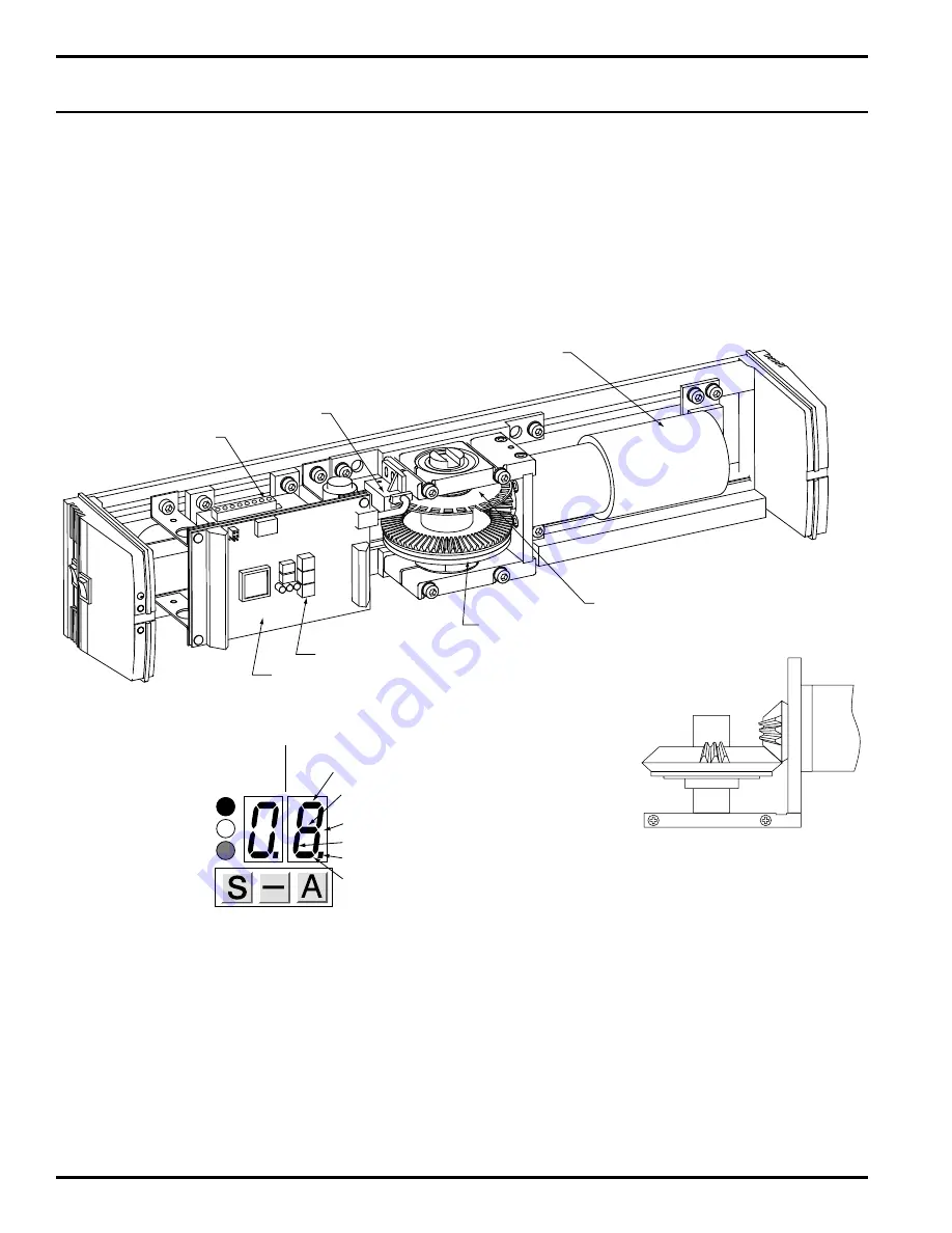
To access the Control Unit, remove the Operator cover.

Display & Program Buttons

In above view, when you press any of the three program buttons, the left display shows the status of the function
switch:

0 = Manual: The door is opened manually, and closed under power.

1 = Auto: The door is opened and closed under power.

2 = Hold Open: The door is held indefinitely at the fully open position.

DIRECT CURRENT -  MOTOR

PULSE DISK 

PULSE COUNTER

FIRE ADAPTER

SAFETY CLUTCH 
AND GEAR ASSEMBLY

PROGRAM BUTTONS

CONTROL UNIT

SAFETY SENSOR

LOCKING CIRCUIT

IMPULSE OUTSIDE

IMPULSE INSIDE

SIGNAL DOT

IMPULSE OUTSIDE INHIBIT

PROGRAM SELECTOR   PULSE DISPLAY 

STATUS                              

RED: ERROR

YELLOW: ADJUSTMENT

GREEN: OK

(SIDE VIEW SAFETY CLUTCH AND
GEAR ASSEMBLY)

Summary of Contents for 2600 Series

Page 1: ...Instructions For Installation and Programming 2600 Series Low Energy Swing Door Operator Push and Pull Applications A7311D ...

Page 2: ...ntrol Unit 14 Display and Program Buttons 14 16 Restore Factory Settings 15 Test the Unit 16 Display LED s 17 Programming a Control Point 18 19 Sealed Control Points 20 Control Points 21 24 Control Points Affecting Speed and Closing Force 25 Programming Suggestions 25 BATTERY OPERATION 26 Fire Door Use 26 Battery Tests 26 Power Failure In Fire Door Mode 27 Fire Adapter 27 FUNCTIONS 27 ELECTRICAL W...

Page 3: ...nit Assembly 1 6 63 3604 Transformer Assembly 1 7 63 3599 Position Sensor 1 8 63 3605 Side Motor Mount 1 9 63 3602 Motor and Drive Gear Assembly 1 10 63 0606 End Cover 1 11 63 3601 Back Motor Mount 1 12 63 3593 Standard Arm 2651 1 13 63 3594 Extended Arm 2652 1 14 63 3595 Track Type Arm 2660 Non Handed 1 15 63 0608 Mounting Plate 1 63 0603 Spindle Extension 3 8 16 63 0604 Spindle Extensions 3 4 1 ...

Page 4: ...weights and widths can be calculated using the formula T D W Where T Time in sec 133 lb ft D Door width in inches W Door weight in lb CLOSING FORCE MUST NOT EXCEED 15 LB FOR A LOW ENERGY APPLICATION IF CLOSING FORCE EXCEEDS 15 LB THE DOOR WILL NOT MEET THE REQUIREMENTS OF ANSI STANDARD A156 19 AMERICAN NATIONAL STANDARD FOR POWER ASSIST AND LOW ENERGY POWER OPERATED DOORS LATCHING SPEED MUST BE SU...

Page 5: ...ay NO NC operation Concealed wiring standard PUSH APPLICATION PULL APPLICATION PUSH APPLICATION PULL APPLICATION Identify your type of application This value will be necessary for programming The 2600 Series Swing Door Operator can be installed in any of four applications CONTROL POINT 14 0 CONTROL POINT 14 1 Identify Door Application GO TO APPLICABLE INSTALLATION INSTRUCTIONS FEATURES AND FUNCTIO...

Page 6: ...erator Housing Removal PUSH Application Mounting Plate Hole Locations 7 7 8 2 3 32 2 7 16 3 3 8 3 4 FROM TOP OF FRAME TOP OF DOOR 22 7 8 4 1 2 7 1 4 2 2 1 2 C OF PIVOT L Opening Angle Max 100 2651 2652 Shown PUSH TYPE APPLICATION INSTALLATION INSTRUCTIONS Step 3 Drill and tap two places door arm foot or slide track holes with a 7 drill Tap holes 12 x 24 PUSH Type Arm Application 13 1 16 1 3 4 TOP ...

Page 7: ...ONDUIT MUST NOT PROTRUDE PAST THE SURFACE MOUNTING PLATE WARNING Ensure that 115VAC power is OFF before touching wires Step 5 Mount the door operator to the mounting plate with four M8x25 screws and washers provided Note Mount the operator with the power switch end cap toward the door hinge MOUNTING PLATE DOOR FRAME DOOR OPERATOR PUSH ARM EXTENSION ARM DOOR ARM FOOT PUSH TYPE APPLICATIONS INSTALLA...

Page 8: ...t and lock washer provided Attach the door arm foot with two screws Position the door arm foot 90 degrees with the door in the closed position and tighten with two 4mm screws 90 HINGE DOOR ARM FOOT DOOR PUSH TYPE APPLICATION INSTALLATION INSTRUCTIONS Step 6 Mount the push arm ...

Page 9: ...to the door frame using four 12 x 24 flat head screws The conduit end of the mounting plate is to be positioned near the hinge side of the frame Step 3 Drill and tap two places door arm foot or slide track holes with a 7 drill Tap holes 12 x 24 PULL Type Arm Application 7 1 8 21 1 8 1 1 8 TOP OF DOOR C OF PIVOT L PULL TYPE APPLICATION INSTALLATION INSTRUCTIONS 7 7 8 2 3 32 2 7 16 3 3 8 3 4 FROM TO...

Page 10: ... CONDUIT FRAME DOOR WALL WHITE BLACK GREEN GND END OF CONDUIT MUST NOT PROTRUDE PAST THE SURFACE MOUNTING PLATE Step 5 Mount the door operator to the mounting plate with four M8x25 screws and washers provided Note Mount the operator with the power switch end cap toward the door hinge DOOR FRAME MOUNTING PLATE DOOR OPERATOR PULL ARM SPACER IF REQUIRED TRACK ROLLER CAP NOT SHOWN PULL TYPE APPLICATIO...

Page 11: ...vided Place door arm roller into track Line up key way of door arm to the operator spindle Attach the door arm to the operator spindle using the longer 8mm bolt provided HINGE DOOR PULL TYPE APPLICATION INSTALLATION INSTRUCTIONS Step 6 Mount or slide track ...

Page 12: ...l connections connect external fire alarm system Note Remove factory installed jumper when connecting to a remote fire alarm system Fire adapter is factory configured for Normally Closed fire alarm contacts TERMINAL BLOCK COVER GREY BROWN BROWN CHASSIS GROUND GREEN YELLOW 115V 230V LINE INPUT SETTING LINE NEUTRAL GROUND POWER SWITCH FACTORY WIRED FOR 120 VOLTS FUSE T 800mA 1 2 3 4 5 6 7 8 9 NO C N...

Page 13: ...te signals the 2600 door operator which retracts the latchbolt s of exit device after a field adjustable preset delay on the operator the door will open External Connections External Connections are connections to remote equipment For example a switch sensor or latch retraction exit device Only voltage free dry contact switches can be used to control the SARGENT 2600 Series Low Energy Swing Door O...

Page 14: ...be properly set with connectors from an approved fire system Check your local code requirements Power Alarm Terminations 1 2 on the Fire Adapter Board Normally Open Contacts close when the main 115 VAC power is disrupted This action is unaffected by the jumper positions or loss of battery power Battery Alarm Jumper JUMPER POSITION FUNCTION OPERATION ON Maintained Low Battery Alarm Normally Open co...

Page 15: ...r cover Display Program Buttons In above view when you press any of the three program buttons the left display shows the status of the function switch 0 Manual The door is opened manually and closed under power 1 Auto The door is opened and closed under power 2 Hold Open The door is held indefinitely at the fully open position DIRECT CURRENT MOTOR PULSE DISK PULSE COUNTER FIRE ADAPTER SAFETY CLUTC...

Page 16: ...er switch to ON The RED LED at the end of the operator should be LIT If light is not lit refer to Restore Factory Settings If the light is lit go to Step 5 STEP 5 Manually rotate the disk in the direction established for CLOSING until the RED LED turns off Opening in disk rim goes into the pulse counter BE CAREFUL Do not over travel RIGHT DISPLAY LEFT DISPLAY RED ERROR YELLOW ADJUSTMENT GREEN OK I...

Page 17: ...CONNECT THE BATTERY BEFORE PROGRAMMING FOR BATTERY OPERATION 1 With 15 displayed press the A button until 0 appears 2 Press A again for a value of 1 Press S to select and set 1 as the value 16 will appear You are now ready to test door operation STEP 7 Test the unit Place the operator function switch to AUTO Turn the power switch to the ON position Press the push plate to activate the door If no p...

Page 18: ...ently inhibited that is not being accepted by the Door Operator Signal dot The signal dot is displayed when a Control Point has been selected using the button The signal dot disappears when a Control Point has been selected and validated by pressing the button DISPLAY LED s The RED LED is lit when an error condition has been detected Refer to Troubleshooting The yellow LED is lit when a Control Po...

Page 19: ...in the displays The yellow LED flashes except for a sealed Control Point The signal dot disappears on the right display 5 To increase the value of the Control Point press the A button To decrease the value of the Control Point press the button 6 When the correct value is displayed press the S button The value is stored in memory The yellow LED remains lit but stops flashing The next higher Control...

Page 20: ...eight 125 lb See Control Point 3 You may have to change one or more of the factory settings to fine tune the Door Operator to your specific application The information you need to program Control Points is presented on the following pages There are three types of Control Points Settings that specify a unit of measure for example seconds Relative values for example a scale of 1 to 10 representing a...

Page 21: ...degrees per unit 02 Latching speed 15 60 15 The angle at which the closing door slows from starting point angle units closing speed to latching speed Recommendation 10 degrees Each unit in the value range approximately 2 degrees See Control Points Affecting Speed and Closure 03 Operator force 1 10 4 The amount of force the Operator applies to Sealed Control Point relative the door to open or close...

Page 22: ... open position 08 Operator acceleration 1 10 4 This setting controls how quickly the Operator time Sealed relative causes the door to accelerate Control Point 1 minimum acceleration time slower 10 maximum acceleration time faster See Control Points Affecting Speed and Closing Note Don t accelerate too fast 09 Closing speed 1 5 3 The speed at which the door moves from the relative fully open positi...

Page 23: ...empts to close the door at intervals of 60 seconds See Control Point 19 See Control Points Affecting Speed and Closure 13 Push and go 1 or 0 1 Turn the Push and Go feature on or off When a pedestrian on off applies manual force to the door and opens it 6 deg the Push and Go feature takes over opening the door 1 Push and Go feature on 0 Push and Go feature off 14 Selection of arm 0 2 1 The standard...

Page 24: ...e latching device is not energized 19 Stall feature 1 or 0 0 Selection of obstruction sensitivity feature operation Closing Direction on off in closing direction 0 The door stops and does not move 1 The door stops then reopens to the fully open position See Control Point 12 20 Hold open force 0 10 0 While the door is fully open the Operator holds it relative against the door stop to prevent the do...

Page 25: ... less in Control Point 07 16 or 17 the door closes automatically when the door opening time expires or If the door opening time is set to 60 sec in Control Point 07 16 or 17 the door does not close until a second impulse is received 26 Cycle Counter 0 00 The counter displays the number of times the 655355 door has cycled opened and closed scrolling two digits at a time starting from the left 27 Se...

Page 26: ...lowest 12 Safety feature sensitivity Too low a value may stop the Together with Control Point 03 it 1 maximum sensitivity door for a few seconds during sets the current level for the 8 minimum sensitivity closing safety feature to be activated When the safety feature activated the door movement is arrested Programming Suggestions Door safety is controlled by basic adjustments particularly Operator...

Page 27: ...the Operator While the Operator power is switched on the Control Unit tests the battery by loading it with 0 4 Amps for 30 seconds Once the battery is fully charged it is tested every 12 hours from then on If voltage rises above 13 VDC the battery is good If the voltage does not rise above 13 V after 24 hours of charging the battery must be replaced After the first test there is no battery alarm f...

Page 28: ...Point 27 6 Lock Control Relay contact ratings Max power 0 8A 30V resistive 0 3A 30V inductive The relay reacts to an opening impulse For relay hold time adjustment see Control Point 22 7 12 and 24V DC Outputs The Control Unit includes a 12 or 24 VDC regulated power supply with Max current 24VDC 0 8 A or 12VDC 0 5 A Power Failure In Fire Alarm Mode If there is a power failure the Door Operator reve...

Page 29: ...28 ELECTRICAL WIRING Typical Application 1 ...

Page 30: ...29 ELECTRICAL WIRING Typical Application 2 ...

Page 31: ...30 ELECTRICAL WIRING Typical Application 3 ...

Page 32: ...31 ELECTRICAL WIRING Typical Application 4 ...

Page 33: ...Aim programmer toward the Power Switch end of the Door Operator and press OK at the LED The hand held programmer will display information about Control Point 0 First two digits 00 the identifier of the Control Point Second two digits the current value of Control Point 00 4 Use the lower and signs to change the value 5 When the correct value is displayed press OK to store the value 6 Use the upper ...

Page 34: ...disappears after a few seconds 3 Set Operator power switch to OFF 4 Turn the Operator pulse disk 1 4 turn in the OPENING direction 5 Set Operator power switch to ON The red LED is lit and the factory settings are restored 6 Rotate the pulse disk in the closing direction until the red LED on the end of the Operator goes off 7 Refer to Quick Start Instructions for programming the Door Operator USING...

Page 35: ... one of the following problems Troubleshooting common start up problems Problem Cause 1 Door operator applies closing force Control Point 14 is set to wrong value of 0 or 1 when activated to open Swap the value to change handing Or Pulse disk was turned in the wrong direction during programming 2 Door does not fully close Check pulse disk closed position 3 Door moves a few inches and then Operator...

Page 36: ...arket leader in locksets cylinders door closers exit devices electro mechanical products and access control systems for new construction renovation and replacement applications The company s customer base includes commercial construction institutional and industrial markets The ASSA ABLOY Group is the world s leading manufacturer and supplier of locking solutions dedicated to satisfying end user n...

Reviews: