background image

4

A7334G

Copyright 

©

 2005, 2008, 2010, 2016, Sargent Manufacturing Company, an ASSA ABLOY Group company. All rights reserved. 

Reproduction in whole or in part without the express written permission of Sargent Manufacturing Company is prohibited.

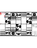
4X 
.422

27/64"

4X 
.625

5/8"

2X 
2.469

2-15/32"

2X 
3.875

3-7/8"

2X
1.765

1-49/64"

2X
6.688

6-11/16"

INSIDE

OF DOOR

3

5

1

7

CL

 OF BEVEL

9

9

6.500

6-1/2"

8.031

8.000

8-1/32"

8"

7.250

7-1/4"

3.625

3-5/8"

4.000

4"

DIM "B"

AA

CL OF LEVER

OR KNOB

MOUNTING SCREWS

2X DRILL 

AND 

TAP FOR

#12-24 x .750 [3/4"] SCREW

CL

 OF DOOR

2X 

2.750

BACKSET

2-3/4"

2X 
1.797

1-51/64"

DIM "C"

.375

3/8"

OUTSIDE

OF DOOR

4

6

8

2

CL OF STRIKE

CL OF

LOCKBOD

Y

CL

 OF BEVEL

5

9

9

.219

7/32"

DIM "A"

SECTION 

A-A

CL

 OF BEVEL

REQUIRED HOLES

FUNCTION

123456789

1.125

[1-1/8"] 

DIA.

1.125

[1-1/8"] 

DIA.

1.375

[1-3/8"] 

DIA.

1.375

[1-3/8"] 

DIA.

.750

[3/4"] 

DIA.

.750

[3/4"] 

DIA.

.250

[1/4"] 

DIA.

.250

[1/4"] 

DIA.

.562

[9/16"]

DIA.

04,
 37

05,
 24,
 25

17,
 26,
 38,
 39,
 40

31,
 35,
 36

65,
 66

RELEASE DA

TE

TEMPLA

TE 

NO
.

100 Sargent Drive New Haven

, CT 06511

Manufacturing Company

TEMPLA

TE:

 MOR

TISE LOCK

8200 SERIES:

 (FREE 

WHEELING)

MET
AL DOOR   


4500

J

NOTES:

 DENOTES HOLE REQUIRED FOR FUNCTION LISTED.

 (CHECK 

TABLE BEFORE CUTTING HOLE.)

1.

REFER 

TO 
TRIM 

TEMPLA

TE FOR 

ADDITIONAL HOLE REQUIREMENTS.

2.

SUIT
ABLE REINFORCEMENTS REQUIRED FOR MET

AL DOORS.

3.

FOR DET

AILS,

 SEE STRIKE 

TEMPLA

TE 7063.

4.

FOR 

WOOD DOORS SEE 

TEMPLA

TE 

A7323.

5.

DET
AIL OF SUGGESTED DOOR-CUT

Summary of Contents for 8200

Page 1: ...rt lockbody into mortise cutout Hold loosely in place with 2 lockbody screws Do not tighten screws fully at this time A With outside lever horizontal carefully insert the mounting posts through the door and lockbody Make sure the spindle is properly engaged in the lock Outside escutcheon assembly should be flush with door surface If cylinder is not included in this function proceed to step 3 B Scr...

Page 2: ...urface of locking piece visible 2 Insert blade type screwdriver into locking piece slot to rotate locking piece 3 Push locking piece toward back of lock body and rotate 180 until RED surface shows on opposite side Note Beveled surface of latch must face strike The deadlatch is self adjusting To change hand of latch 1 Insert screwdriver blade into the spade shaped slot 2 Rotate screwdriver 90º to p...

Page 3: ...Position hub 4 for required function and hand checking that spindle 5 is vertical Note position of interlocking assembly Hook when positioning hub Reposition spindle as shown in Figure D if necessary 11 Place the interlocking assembly 2 into the escutcheon and attach the bottom hook to the locking hub 8 as shown in Figure B Secure in place with screw 1 Caution Check that locking hub 4 moves freely...

Page 4: ...C 375 3 8 OUTSIDE OF DOOR 4 6 8 2 C L OF STRIKE C L OF LOCKBODY C L OF BEVEL 5 9 9 219 7 32 DIM A SECTION A A C L OF BEVEL REQUIRED HOLES FUNCTION 1 2 3 4 5 6 7 8 9 1 125 1 1 8 DIA 1 125 1 1 8 DIA 1 375 1 3 8 DIA 1 375 1 3 8 DIA 750 3 4 DIA 750 3 4 DIA 250 1 4 DIA 250 1 4 DIA 562 9 16 DIA 04 37 05 24 25 17 26 38 39 40 31 35 36 65 66 RELEASE DATE TEMPLATE NO 100 Sargent Drive New Haven CT 06511 Man...

Reviews: