Passport 1000 P2 WiFi Exit Device
Copyright © 2014, Sargent Manufacturing Company
, an ASSA ABLOY Group company
. All rights reser
ved.
Reproductions in whole or in part without express written permission of Sargent Manufacturing Company is prohibited.
03/31/14
18 1-800-810-WIRE • www.sargentlock.com • A8012F
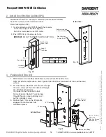
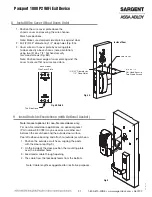
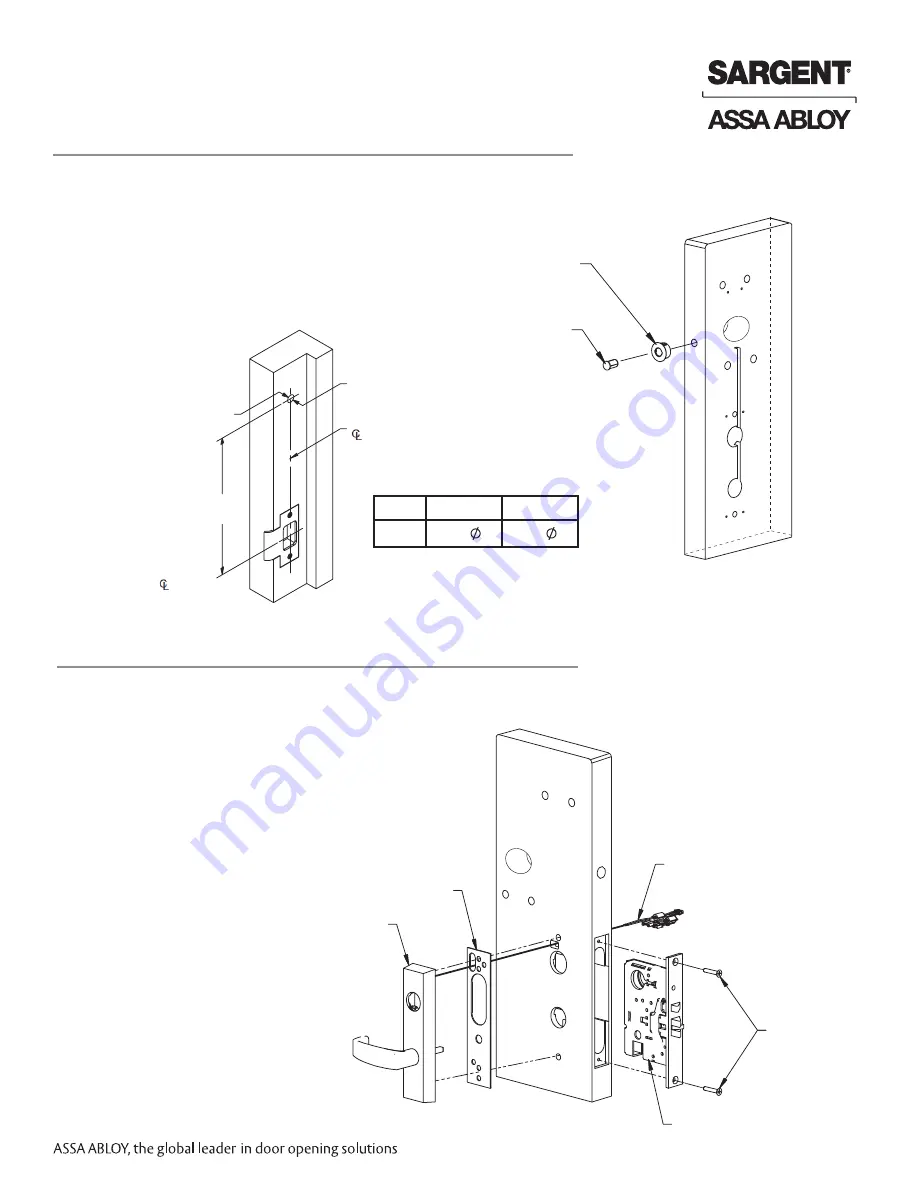
Fig. 2A
Collar is used only
with metal doors.
Door Position
Switch (DPS)
Inside of Door
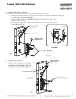
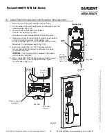
Fig. 3A
(2) 1/4” x 2-3/8”
Flat Head
Machine Screws
(Secures ET)
Wire Harness
(From motor)
Mortise Lock Body
ET Control
ET Control
Outside of Door
1. Slide mortise lock into door and loosely secure with (2) flat head screws.
Note: For exterior applications, use ET gasket (52-0263) to seal between ET trim and the door
surface.
2. For wood doors: Route ET wire harness through
the wire cutout, out the other side and through
the Wire Run Channel (on
the inside) to the Controller Cutout.
For metal doors: Route ET wire harness
through the wire cutout and door and
out the controller cutout.
3. Position the ET trim so the ET spindle
engages the mortise lock hub
and hold in place.
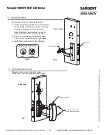
Wood doors have 3/8” raceway to controller cutout and metal doors
have 3/4” raceway to the controller cutout.
Refer to template A7951.
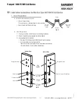
1. Insert connector end of DPS through the raceway
on the latch edge of the door (Fig.6A).
Note: For metal doors, use DPS Collar.
2. Push DPS firmly into place by hand.
IMPORTANT
: DO NOT TAP SWITCH WITH ANY TOOL.
Wood Frame
Metal Frame
Dim 1
3/8”
3/4”
Horizontal
of Strike
Door Position
Switch Hole
Vertical
of Strike
Dim 2
(From template)
Dim 1
Fig. 2B
2 Install Door Position Switch (DPS)
3 Position Exit Trim (ET)


