SARK
SARK
SARK
SARK-
-
-
-110
110
110
110
User’s Manual
Rev 1.2.6 October 3
rd
, 2015
- 69 -
© Melchor Varela – EA4FRB 2011-2015
Appendix A:
Theory of Operation
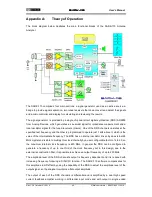
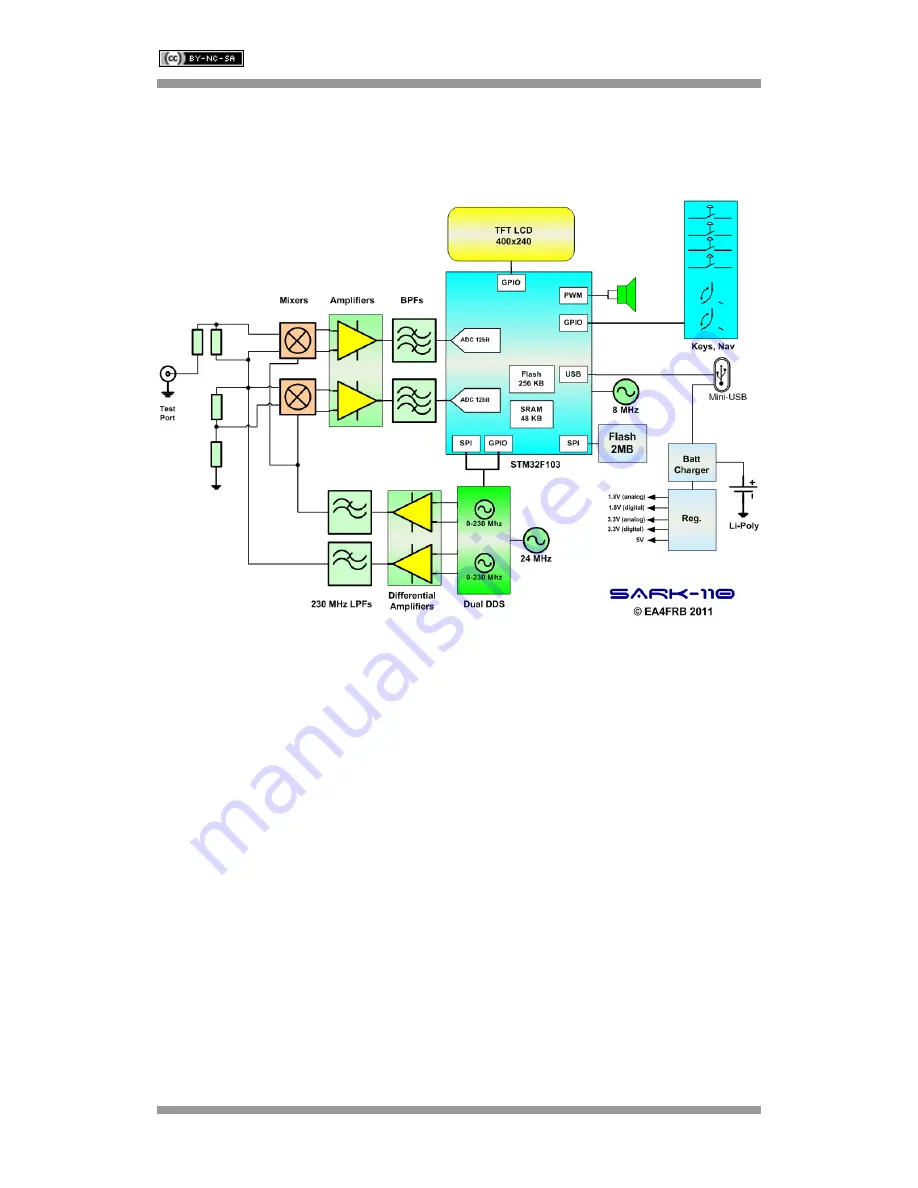
The block diagram below illustrates the main functional blocks of the SARK-110 Antenna
Analyzer:
The SARK-110 comprises four main sections: a signal generator used as an active source, a
bridge to provide signal separation, two tuned receivers that downconvert and detect the signals
and a microcontroller and display for calculating and reviewing the results.
The signal generator is provided by a single chip dual direct digital synthesizer (DDS) AD9958
from Analog Devices, which generates a sinusoidal signal for impedance measurement and a
local oscillator signal for the tuned receivers (mixers). One of the DDS channels operates at the
specified test frequency and the other is programmed to operate just 1 kHz above it, which is the
value of the intermediate frequency. The DDS has an internal oscillator driven by an external 24
MHz crystal and is able to multiply this clock internally by a user configurable factor of 4 to 20, so
the maximum internal clock frequency is 480 MHz. In general the DDS can be configured to
generate a frequency of up to one third of the clock frequency but in this design, due to the
external reconstruction filter, it is possible to achieve an output frequency of up to 230 MHz.
The amplitude level of the DDS channel’s output is frequency dependent and it is reduced with
increasing frequency following a SIN(X)/X function. The SARK-110 software compensates for
this amplitude rolloff effect by using the capability of the DDS to adjust the amplitude level of the
output signal, so the analyzer maintains a flat output amplitude.
The output of each of the DDS channels is differential and is amplified by a dual high speed
current feedback amplifier working in differential input mode and with output in single ended

