background image

                                                                                                    User Manual


Version 1.2


12 

Step 6: Turn on power switches 

Turn on the Power Switches on the rear panels of both RX and TX. Wait for about 

10 seconds.   

A red Power Indicator light will illuminate on the front panel of both the Transmitter 

and Receiver.  The Source LED indicator on the TX will show which of the 

available input connectors is currently in use  

Source LED indicators on front panel: 

HDMI connector 1  

AV1 

CVBS/S-Video 

AV2 

YPbPr connectors 


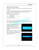
In our example we connected the Blu-Ray player to HDMI #3, so the Source LED 

indicator “HDMI 3” should illuminate. 

Meanwhile, at the TV, you may see a couple 

of messages display on the TV screen 

(depending on boot up sequence of 

equipment).  These include a “Welcome” 

message or “Waiting for TX to be ready” 

message. 

After booting all of your equipment (TV, Blu-

Ray, TX and RX), the video transmission from 

the source Blu-Ray player should begin to 

display within 40 seconds. 


Summary of Contents for HD-18

Page 1: ...User Manual Version 1 2 1 HD 18 User Manual Version 1 2 Powered by Technology...

Page 2: ...ler 16 6 OSD Menu 19 7 Adding an Additional RX 21 8 Running TX as a Standalone Box 22 9 Running Multiple Transmitters with Multiple Receivers 23 Appendix 1 RX TX Pairing 25 Appendix 2 PLC Pairing 26 A...

Page 3: ...e certified to repair these devices If your device needs repair please contact your dealer Do not place containers holding liquid e g flower vases coffee mugs etc or material soaked with moisture e g...

Page 4: ...e between the case and surrounding items e g walls furniture closets etc Do not place things on the power line or drag anything over it If the power line is damaged replace it immediately to prevent e...

Page 5: ...t irreparably Unauthorized repair by uncertified repair facilities is forbidden If the device is accidently exposed to water or the case is damaged in any way turn off the power switch and unplug the...

Page 6: ...your Transmitter while your HDTV is connected to the Receiver both Receiver and Transmitter are connected to Power Outlets PowerHDLink also allows you to use IR Remote Controllers to control A V equip...

Page 7: ...setup you will also need TV Standard or HDTV with HDMI YPbPr or CVBS connectors Video player e g Blu Ray player DVD player with HDMI YPbPr or CVBS S Video connectors Two available power outlets IMPOR...

Page 8: ...User Manual Version 1 2 8 This guide will use an HDTV and a Blu Ray player as the video equipment in the examples...

Page 9: ...each color coded green blue and red Simply match the colors on the connectors with the color coded adapters on the Transmitter Since YPbPr video cable doesn t carry audio you must also attach an audi...

Page 10: ...2 Connect the HDTV set to the Receiver Connect your PowerHDLink receiver to the HDTV The receiver is capable of using HDMI YPbPr and CVBS cables You must choose from one those options as shown below...

Page 11: ...isc player Power on your TV set and Blu Ray Player in any order Place a Blue Ray video disc into the player Step 4 Connect the power cables to the TX and RX Connect one end of the TX power cable to th...

Page 12: ...e Source LED indicators on front panel 1 HDMI connector 1 AV1 CVBS S Video AV2 YPbPr connectors In our example we connected the Blu Ray player to HDMI 3 so the Source LED indicator HDMI 3 should illum...

Page 13: ...o make sure the TV that is attached to the TX is in working order Make sure that the Source LED indicator matches the physical connection between the TX and player that is connected to it The LED indi...

Page 14: ...the right will instruct you on how to proceed in order The Video displaying diamond refers to video on the TV attached to the RX The procedures in the boxes are explained in the Appendices as listed b...

Page 15: ...signals and sends them over the power lines to the TX where the TX re emits the same IR signals to the video player Step 1 Attach IR Blaster Cable to TX Connect the IR Blaster Cable to the back of th...

Page 16: ...a remote location i e where receiver is located The receiver accepts IR signals from the Remote Controller and passes them to the transmitter through the power lines The Remote Controller can also br...

Page 17: ...his button if the RX and TX cannot establish a connection cannot be paired You also need to use this button when adding an additional RX to your existing RX TX environment or group This button is also...

Page 18: ...me on the receiver Setting Move right for RX Move to right button on the OSD Menu Setting Setting confirmation for RX This button is like the Enter key used to confirm a setting selection Setting Move...

Page 19: ...options as described below OSD Menu SETUP Items AV1 Video Select Language Network Bandwidth Resolution Control Sleep Time LIP SYNC Information Navigating the OSD Menu You can navigate the OSD Menu usi...

Page 20: ...ndwidth you can simply choose the Auto Detect option Auto Detect Low Fair Good Excellent Resolution Control Selects the output resolution for the display By Source By TV Sleep Time Sets the amount of...

Page 21: ...can attach up to 4 RX s for one TX Every time you add an additional RX to your system you must perform the procedures below in order 1 Reset RX PLC to Factory Defaults Refer to Appendix 4 2 PLC Pairin...

Page 22: ...you can simply turn off the RX and the TX becomes a standalone system However if both TX and RX are initially turned off turn on your TV and then turn on your TX After the TX has gone through its ini...

Page 23: ...ng to a different transmitter Selecting a different TX source for a RX 1 On the remote at the RX press the Menu button to open the OSD menu Use the up down arrow buttons to move to the Select TX Stati...

Page 24: ...cursor position Use the and the buttons to select a certain character alphabet or numeric Use the button to move back one space deleting one character Use the button to confirm the character selection...

Page 25: ...til the PAIRING message displays on the TV attached to the RX 2 Press the Group button on the rear panel of the TX for 2 seconds If the link is successful the message on the TV screen will change from...

Page 26: ...ress the Link button on the remote controller at the TX and RX A Doing PLC Grouping message will display on the TV at the RX If the link is successful the video will begin to display on the remote TV...

Page 27: ...utton at rear panel of TX for about 6 seconds until all the LEDs flash off on off on The TX will be reset to the system factory default settings b At the RX press the Group Button on the remote contro...

Page 28: ...press the Factory Button on the remote controller AT LEAST 3 TIMES in rapid succession until all the source LEDs on the front panel go off on off on and the system will reboot automatically b At the R...

Page 29: ...ia source player can work directly with the TV it might indicate a problem with the video audio format Check Appendix 6 Video Specifications to make sure the video format delivered by the player is su...

Page 30: ...t paired please do pairing message If so pair the TX and RX Appendix 1 Media source player is not powered on or is in standby mode Check to see if the media source player is turned on Check to see if...

Page 31: ...the format used by the TX in this case there are usually no problems However if the Media source had been manually configured to send a certain format that is not supported by the TX you will need to...

Page 32: ...1 1 AV PLC PLC Bridge Function 1 1 IR sensor port 1 1 Remote Controller 1 IR Blaster port 3 IR Blaster cable 1 38 kHz AC Power Input 100 240V 50 60 Hz 0 2A max Power Consumption 12W 9W average Operati...

Reviews: