background image


 Transmitter x 1 

 Receiver x 1 

 Infrared (IR) eye cable x 1 

 Audio/Video cable x 2 

 Power adaptors (DC6V) x 2 

 User manual x 1 

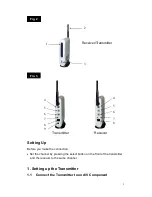
    Note: The transmitter and the receiver look very similar.    You can find   

                “transmitter” and “receiver” labels on the side of the units. See Fig. 1. 


Product Layout 

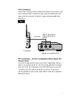
Transmitter/Receiver (See Fig. 2 and Fig. 3) 

1.  Power/Channel Indicator/IR Window 

2.  Audio/Video Antenna 

3.  Channel Select Button (Select the channel by pressing the tact switch to 

the channel number you want.   

Note:

 Must select the same channel both 

on the transmitter and the receiver). 

4.  Audio Jack (Red) 

5.  Audio Jack (White) 

6.  Video Jack (Yellow) 

7.  Power On/Off 

8.  Power Adaptor Plug   

9.  IR Eye 


Fig. 1 

Transmitter 

Receiver 

Receiver 

Transmitter 

Summary of Contents for SR-09

Page 1: ...2 4 2 5GHz Wireless Audio Video Sender User Manual SR 09 Package Contents...

Page 2: ...e Fig 1 Product Layout Transmitter Receiver See Fig 2 and Fig 3 1 Power Channel Indicator IR Window 2 Audio Video Antenna 3 Channel Select Button Select the channel by pressing the tact switch to the...

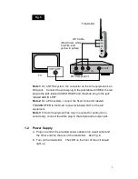
Page 3: ...by pressing the select button on the front of the transmitter and the receiver to the same channel 1 Setting up the Transmitter 1 1 Connect the Transmitter to an A V Component Fig 2 1 2 3 4 5 6 7 Rec...

Page 4: ...Output Jacks If your A V component has only one set of A V output jacks and you want to use it with a nearby TV connect coaxial cable from the signal OUT port on the A V component to the VHF UHF IN p...

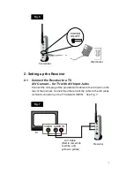
Page 5: ...nector labeled OUT on the A V equipment Note 3 If the A V equipment has only one output for audio mono sound only connect the white plug to that single audio output jack 1 2 Power Supply a Plug one en...

Page 6: ...plug of the provided A V cables to the A V jack on the rear of the receiver connect the other end of the cable to the A V jacks or Scart connector on the TV labeled LINE IN See Fig 7 POWER ON OFF Tra...

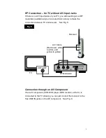
Page 7: ...nnection between TV and receiver See Fig 8 Connection through an A V Component If an A V component VCR DVD player DBS receiver and etc is connected to the TV already you can just connect the receiver...

Page 8: ...ect the white plug to that single audio in jack 2 2 Power Supply a Plug one end of the provided power adaptor into a wall outlet and the other end into the rear of the receiver See Fig 10 b Turn on th...

Page 9: ...e to the A V source component and plug the IR eye into the jack located on the rear of the transmitter IR Eye plug Adhere the IR eye directly to the IR window on the front of the source component see...

Page 10: ...tter receiver Weight 125g for transmitter receiver Power DC6V 500mA Operating Temperature 0 40 32 104 Providing the latest technologies to our customers is our responsibility therefore we reserve the...

Page 11: ...g parts may be damaged Do not store in hot areas High temperatures can shorten the life of electronic devices and warp or melt certain plastics Do not store in very cold areas When the A V sender warm...

Page 12: ...11 caused by unauthorized modifications to this equipment Such modifications could void the user s authority to operate the equipment...

Reviews: