Minimum Load for Initialization and
Defining the Class 1 Lower Limit
The minimum load defines the
lower limit for Class 1 (i.e., the delimiter
between Classes 0 and 1). The appli-
cation can only be initialized (to define
the upper limit of Class 1) when
the load on the weighing instrument
exceeds the minimum load.
Display
The result of a given measurement
is shown as either a weight value
or the class number. You can toggle
between these two display modes
by pressing
w
.
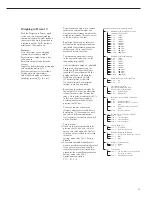
– Weight display; 3 classes:
The current weight is shown in the
display; for example: 108.7 g
Class 1
Bar graph:
Numeric display:
1
LED: red is lit
Class 2
Bar graph:
Numeric display:
2
LED: green is lit
Class 3
Bar graph:
Numeric display:
3
LED: yellow is lit
– Weight display; 5 classes
The current weight is shown in the
display; for example: 108.7 g
Class 1
Bar graph:
Numeric display:
1
LED: red is lit
Class 2
Bar graph:
Numeric display:
2
LED: red and green are lit
Class 3
Bar graph:
Numeric display:
3
LED: green is lit
Class 4
Bar graph:
Numeric display:
4
LED: green and yellow are lit
Class 5
Bar graph:
Numeric display:
5
LED: yellow is lit
– Class display; 3 classes
The current class is shown in the
display; for example:
class 1
and the
bar graph indicates the current weight.
The LEDs are lit as for the weight
display described above.
– Class display; 5 classes
The current class is shown in the
display; for example:
class 1
, and the
bar graph indicates the current weight.
The LEDs are lit as for the weight
display described above.
41
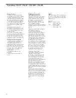
Digital Input/Output Interface
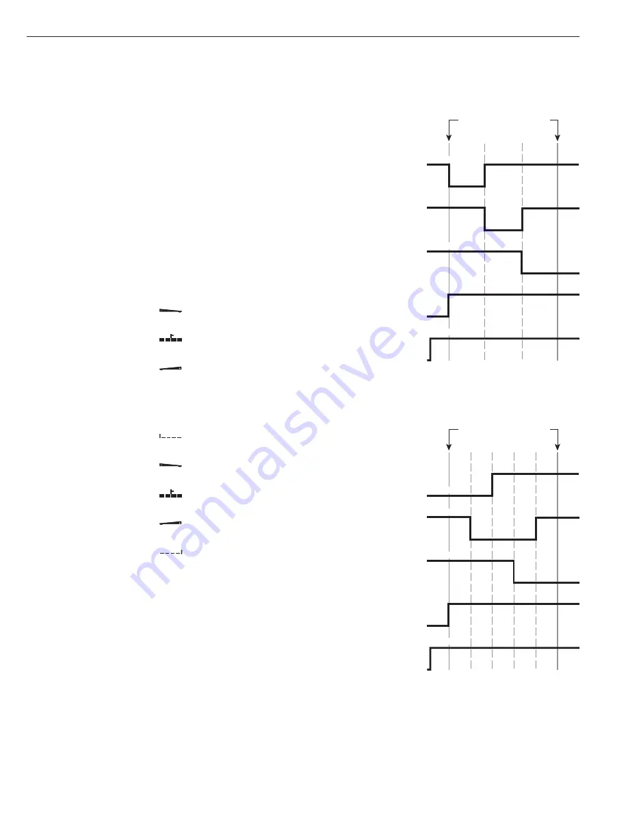
The Classification application supports
the digital input/output-interface.
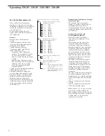
There are 4 control lines, or outputs,
which are activated as follows (also refer
to the diagram):
– Lighter
– Equal
– Heavier
– Set
The “Set" line usually indicates that the
minimum load is exceeded. Alternatively,
you can assign the “Ready-for-use"
function to this port.
Under menu item 4.7, you can define
whether these control ports are
– inactive (4.7.1),
– always active (4.7.2), or
– active at stability (4.7.3).
This makes it possible, for example,
to connect a simple indicator for
weighing or calculation results, similar
to the 3-segment checkweighing
display on the Combics, or control
an automatic process.
Digital I/O Interface
Control lines when working with 3
classes
Digital I/O Interface
Control lines when working with
5 classes
Class
1
2
3
Min. load
Max. load
Class 2
Set
Class 1
Class 3
Operative
Class
1
2
3
4
5
Min. load
Max. load
Set
Classes 1/2
Classes 4/5
Operative
Classes 2/3/4
Summary of Contents for CH1NE
Page 102: ...CH Platform Dimensions Scale Drawings CH G CH E 102 ...
Page 108: ...108 ...
Page 109: ...109 ...
Page 110: ...110 ...
Page 111: ...111 ...
Page 112: ...112 ...
Page 113: ...113 ...
Page 114: ...114 ...
Page 115: ...115 ...
Page 116: ...116 ...
Page 117: ...117 ...
Page 118: ...118 ...
Page 120: ......


