background image

Safety Information

§

Please read these operating instructions
carefully before using your indicator. 
The manufacturer accepts no liability
for damage occurring as a result of 
failure to observe the warnings and
safety information in this manual.
The explosion-protected model CIXS3
indicator meets the requirements for
Group II, Category 1 (dusts) and Cate-
gory 2 (gases) equipment in accordance
with EC Directive 94/9/EEC and bears
the designation 

h

II 2 G 1 D EEx ib IIC

T4 T135°C in accordance with KEMA
EC type-examination certificate
03ATEX1157X. Furthermore, this
weighing system meets the EC Direc-
tives for electromagnetic compatibility
(see the Declaration of Conformity in
the enclosed installation instructions). 
Improper use or handling, however, can
result in damage and/or injury. The
indicator may be used and operated by
qualified personnel only.

!

In Germany, the intrinsically safe 
indicator can be used in Zone 1 and 2
hazardous areas (gases) and Zone 20,
21 and 22 hazardous areas (dusts).
Whether the equipment can be used in
a given area containing potentially
explosive agents must be checked on 
a case-by-case basis. Installation in a
Zone 1, 2, 20, 21 or 22 hazardous area
must be performed by a trained techni-
cian in accordance with the laws, guide-
lines and standards valid in your coun-
try. Always comply with the applicable
regulations for accident prevention. The
trained technician must be familiar with
the assembly, start-up and operation of
the system, and must furthermore have
the required qualifications and be famil-
iar with the relevant guidelines and reg-
ulations in effect in your country. If you
need assistance, contact your Sartorius
dealer or the Sartorius Service Center. 

!

Operating the indicator beyond the
specifications listed in the type-
approval certificates is not permitted,
and is considered use of the equipment
for other than its intended purpose. All
specifications and restrictions listed in
the type-examination certificates must
be strictly observed (see “Documents for
Hazardous Areas” in the operating
instructions). 
Any installation work that does not
conform to the instructions in this man-
ual will result in forfeiture of all claims
under the manufacturer’s warranty.

– Have the equipment inspected at appro-

priate intervals for correct functioning
and safety by a trained technician.

– Always make sure the CIXS3 is discon-

nected from AC power before performing

3

Warnings and Safety Precautions

any installation, cleaning, maintenance
or repair work. If the equipment hous-
ing is opened by anyone other than per-
sons authorized by Sartorius, this will
result in forfeiture of all claims under
the manufacturer’s warranty. Use only
original Sartorius spare parts.

– Do not expose the equipment to

aggressive chemical vapors or to
extreme temperatures, moisture, shocks,
or vibration. The allowable temperature
range during operation is -10°C to
+40°C (14°F to 104°F).

– If you use cables purchased from anoth-

er manufacturer, check the pin assign-
ments in the cable against those speci-
fied by Sartorius before connecting the
cable to Sartorius equipment, and dis-
connect any wires that are assigned dif-
ferently. The operator shall be wholly
responsible for any damage or injuries
that occur when using cables not sup-
plied by Sartorius.

– When using the equipment in hazardous

areas, make sure there is no current or
voltage in the equipment before con-
necting or disconnecting current-carry-
ing cables to or from the device. 
Disconnect the weighing equipment
from AC power before connecting or
disconnecting cables.

– Avoid exposing the equipment (espe-

cially the dust cover) to static electricity;
be sure to connect the equipotential
bonding conductor. 

– Disconnecting equipotential bonding

conductors is not permitted.

– If you see any indication that the equip-

ment cannot be operated safely, discon-
nect the system from power and lock
the equipment in a secure place so that
it cannot be used for the time being.
Observe the relevant safety precautions
and inform personnel as required. 

!

Make sure you disconnect the power
supply from the mains (wall outlet)
before connecting or disconnecting
peripheral devices to or from the 
indicator.

– The casing on all connecting cables, 

as well as the casing on wires inside the
equipment housing, is made of PVC.
Chemicals that corrode these materials
must be kept away from these cables.

– When connecting the CIXS3 to other

equipment, make sure to observe the
specifications listed in the type-approval
certificates. For more information, 
see the “Certificate of Proof of Intrinsic
Safety” in the appendix to the operating
instructions.

Installation

– Proceed with extreme caution when

using pre-wired RS-232 connecting
cables, as the pin assignments may not
be compatible with Sartorius equip-
ment. Before connecting the cable,
check all pin assignments against the
cabling diagrams and disconnect any
lines that are assigned differently.

!

Use only standard cables that have 
protective grounding conductors. 
The protective conductor must not be
disconnected for any reason.

!

If there is visible damage to the equip-
ment or power cord, disconnect the
equipment from power and lock it in 
a secure place to ensure that it cannot
be used for the time being.

– Connect only Sartorius accessories and

options, as these are optimally designed
for use with your indicator. On request,
Sartorius will be happy to provide 
information on operating specifications
(in accordance with the Standards for
defined immunity to interference).

$

If you have any problems with your
indicator, please contact your local 
Sartorius office, dealer or service center.

IP Rating: 

– The IP65/IP67 protection rating for the

indicator is ensured only if the rubber
gasket is installed and all connections
are fastened securely (including the caps
on unused sockets). Weighing platforms
must be installed and tested by a certi-
fied technician.

– If you install an interface port after set-

ting up your indicator, keep the protec-
tive cap in a safe place to be used for
protecting the interface port when not
in use or prior to shipment. The cap
protects the data interface connector
from vapors, moisture and dust or dirt.

Using the Equipment 
in Legal Metrology in the EU*

– When the indicator is connected to a

weighing platform and the resulting
weighing instrument is to be verified,
make sure to observe the applicable
regulations regarding verification.
Please read the brochure entitled “Guide
to Verification” on the CD enclosed with
the operating instructions and observe
all guidelines contained therein. When
connecting a Sartorius weighing plat-
form, make sure to observe the permit-
ted weighing range as listed in the 
Declaration of Conformity.

– If any of the verification seals are dam-

aged, make sure to observe the national
regulations and standards applicable in
your country in such cases. In some coun-
tries, the equipment must be re-verified.

* including the Signatories of the Agree-

ment on the European Economic Area

Summary of Contents for Combics 3 CIXS3

Page 1: ...icheres Auswerteger t f r explosionsgef hrdete Bereiche Mod le EX CIXS3 Indicateur s curit intrins que pour domaines risques d explosions Modello CIXS3 con protezione antideflagrante Indicatore a sicu...

Page 2: ...mbics is switched on Automatic taring when a load is placed on the weighing platform Optional control through an external computer Combics indicators save work and speed up routine applications throug...

Page 3: ...t before con necting or disconnecting current carry ing cables to or from the device Disconnect the weighing equipment from AC power before connecting or disconnecting cables Avoid exposing the equipm...

Page 4: ...memory see Pin Assignment Charts in the operating instructions 6 Activating the interface printer or Alibi memory in the indicator Setup menu refer to the operating instructions and configure the foll...

Page 5: ...tion program application specific information 7 Data output key 8 Gross net 2nd unit or 10 higher resolution depending on the settings 9 Tare key 10 Zero key 11 Toggle to different weighing platform 1...

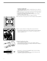
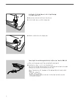
Page 6: ...nt panel and remove the panel Use the connecting cable from the weighing platform to connect the indicator The cable gland is installed at the factory Please use extreme caution when performing any wo...

Page 7: ...hazardous area Note Install both cables so that they are stationary Devices suitable for flexible cable installation available on request YPS02 Z for use outside the hazardous area Connecting the Exte...

Page 8: ...2 X Disconnect the equipment from AC power unplug the power supply Installation in a Zone 1 2 20 21 or 22 hazardous area Plug connector A from the indicator into connector B from the external recharge...

Page 9: ...y and any other cables from the indicator Make sure that no liquid enters the indicator housing Do not use aggressive cleaning agents solvents or similar agents Avoid static electricity Clean the indi...

Page 10: ...Standort der W geplattform Kennzeichnung der W geg ter mit bis zu 4 alphanumerischen Bezeichnern Flexibilit t durch unterschiedliche Schnittstellen Sicherheit durch Codewort Schutz Leichtes Reinigen...

Page 11: ...bers Beim Einsatz des CIXS3 im explosions gef hrdeten Bereich d rfen alle Strom f hrenden Kabel nur im strom span nungslosen Zustand von dem Ger t gezogen oder aufgesteckt werden Vor Anschluss oder Tr...

Page 12: ...tellen Druckzeilen bereiche f r jeweiligen Drucker in der Bedienungsanleitung 7 Der RS 422 RS 485 Datenausgang an COM2 darf nur dann benutzt werden wenn an COM2 der RS 232 Datenaus gang nicht angeschl...

Page 13: ...ngspro gramm Anwendungsspezifische Informationen 7 Datenausgabe 8 Brutto Netto 2 Einheit oder 10 fach h here Aufl sung je nach Voreinstellung 9 Tarieren 10 Nullstellen 11 W geplattform wechseln 12 Ein...

Page 14: ...r Frontplatte l sen Frontplatte abnehmen W geplattform mit Auswerteger t verbinden Die Kabelverschraubung ist vormontiert Alle Arbeiten an der Verschraubung vorsichtig durchf hren Einen Drehmomentschl...

Page 15: ...sionsgef hrdeten Bereich YPS02 XV24 24V Netzmodul zur Installation im explosionsgef hrdeten Bereich Hinweis Beide Kabel fest verlegen Ger teversion f r eine flexible Kabelverlegung auf Anfrage YPS02 Z...

Page 16: ...hlie en Zubeh r YRB02 X Auswerteger t von der Spannungsversorgung trennen Installation in Zone 1 2 20 21 oder 22 Die Steckverbinder A vom Auswerteger t und B vom Akku Pack fest verschrauben Die Betrie...

Page 17: ...langen Keine aggressiven Reinigungsmittel L sungsmittel o verwenden Elektrostatische Aufladung vermeiden Auswerteger t mit in Seifenlauge leicht angefeuchtetem Tuch reinigen Bei Einsatz in der Lebensm...

Page 18: ...pes e Possibilit d identifier facilement les chantillons peser avec jusqu 4 ID alphanum riques Flexibles dans leur utilisation gr ce diff rentes interfaces Assur s contre toute modification non autori...

Page 19: ...ne doivent tre tir s ou branch s que lorsque la balance est hors tension Avant de connecter ou de retirer des c bles d brancher la balance Eviter les charges lectrostatiques connecter la borne de com...

Page 20: ...ante respective dans le mode d emploi 7 Vous pouvez utiliser le connecteur d interface RS422 RS485 sur COM2 uniquement si le connecteur d interface RS232 n est pas raccord COM2 En d autres mots il n e...

Page 21: ...plication 7 Sortie des donn es 8 Brut Net 2 me unit ou r solution 10 fois sup rieure selon le r glage 9 Tarage 10 Mise z ro 11 Changement de plate forme de pes e 12 Mise en marche Arr t 13 Touches de...

Page 22: ...dicateur est d j mont Retirer la plaque avant d visser les 4 vis de la plaque avant Connecter la plate forme de pes e l indicateur Le presse toupe est d j mont Tous les travaux de raccordement doivent...

Page 23: ...XV24 module 24V pour l installation dans un domaine risques d explosions Remarque poser les deux c bles demeure version d appareils pour une pose flexible des c bles sur demande YPS02 Z pour l install...

Page 24: ...fication Raccordement de l accumulateur externe accessoire YRB02 X D brancher l indicateur de l alimentation en courant Installation dans la zone 1 2 20 21 ou 22 Raccorder les connecteurs A de l indic...

Page 25: ...dicateur du secteur ainsi que le c ble de transmissions des donn es Veillez ce qu aucun liquide ne p n tre l int rieur de l appareil Ne pas utiliser de produits de nettoyage corrosifs d tergents ou pr...

Page 26: ...zione della piattaforma di pesata Identificazione dei campioni di pesata mediante 4 codici alfanumerici Diverse interfacce per un utilizzo versatile Sicurezza grazie alla protezione con password Facil...

Page 27: ...taccare lo strumento dalla rete elettrica Evitare il formarsi di cariche elettrostati che collegare un morsetto del condut tore equipotenziale vietato staccare il conduttore di messa a terra Se Vi sem...

Page 28: ...otocollo di stampa Campi e righe di stampa per la stam pante corrispondente nel manuale di istruzioni per l uso 7 Potete utilizzare il connettore d inter faccia RS422 RS485 su COM2 solo se il connetto...

Page 29: ...e dell applicazione 7 Uscita dati 8 Lordo Netto 2 unit oppure risoluzione 10 volte pi alta dipende dall impostazione 9 Taratura 10 Azzeramento 11 Commutazione della piattaforma di pesata 12 Accensione...

Page 30: ...il pannello frontale svitare le 4 viti Collegare il cavo di sistema della piattaforma di pesata all indicatore Il pressacavo preinstallato Tutti i lavori sul pressacavo devono essere eseguiti con molt...

Page 31: ...ell area a rischio di esplosione Nota montare i cavi in modo fisso Su richiesta disponibile la versione dello strumento per un montaggio flessibile del cavo YPS02 Z per l installazione nell area sicur...

Page 32: ...o dell unit di batterie ricaricabili esterne accessorio YRB02 X Staccare l indicatore dalla alimentazione Installazione nelle Zone 1 2 20 21 oppure 22 avvitare insieme il connettore ad innesto A dell...

Page 33: ...collegato anche il cavo per la trasmissione dei dati Non deve entrare liquido all interno dell indicatore Non utilizzare detergenti aggressivi solventi o simili Evitare le cariche elettrostatiche Pul...

Page 34: ...lugar respecto a la c lula de carga Identificaci n de las muestras con 4 ID alfanum ricos m ximo Flexibilidad con diferentes interfaces Seguridad con entrada de contrase a Limpieza y desinfecci n f c...

Page 35: ...n la zona con peligro de explosi n todos los cables conductores de corriente tienen que separarse o enchufarse del en el aparato encontr n dose ste separado de la tensi n de red Antes de conectar o se...

Page 36: ...r protocolo de impresi n L neas de impresi n reas para la impresora respectiva en las instrucciones de funcionamiento 7 Puede utilizar el conector de interfaz RS422 RS485 en COM2 s lo si el conec tor...

Page 37: ...ograma de aplicaci n informaciones espec ficas de aplicaci n 7 Salida de datos 8 Bruto neto 2 unidad o bien resoluci n factor 10 seg n ajuste previo 9 Tara 10 Puesta a cero 11 Conmutar c lula de carga...

Page 38: ...e la placa de base Retirar la placa de base Enlace de la c lula de carga con el visor La borna atornillable ya est premontada Todos los trabajos en la borna atornillable han de realizarse con extremo...

Page 39: ...eligro de explosi n YPS02 XV24 24V m dulo de red para la instalaci n en la zona con peligro de explosi n Advertencia tender ambos cables en forma fija versi n de aparato para un tendido de cables flex...

Page 40: ...ipo de bater a externo accesorio YRB02 X Separar el visor de la alimentaci n de tensi n Instalaci n en la zona 1 2 20 21 22 Atornillar fijamente los conectores de enlace A del visor y B del equipo de...

Page 41: ...ar detergentes de limpieza agresivos disolventes o similares Evitar cargas electrost ticas Limpiar el visor con un pa o suave humectado levemente en agua jabonosa Al utilizar en la industria alimentar...

Page 42: ...lijk van de opstelplaats van het weegplatform Markeren van weeggoederen met max 4 alfanumerieke codes Flexibiliteit door verschillende interfaces Veiligheid door wachtwoordbeveiliging Gemakkelijk te r...

Page 43: ...toestand van het appa raat losgemaakt of erin gestoken wor den Voor het aansluiten of losmaken van kabels dient de weegschaal eerst van het spanningsnet te worden losge koppeld Vermijd elektrostatisc...

Page 44: ...Printerprotocol instellen Afdrukregels bereik voor de betreffende printer in de handleiding 7 De RS422 RS485 uitgang op COM2 mag alleen worden gebruikt wanneer de RS232 uitgang niet op COM2 is aangesl...

Page 45: ...gramma Toepassingsspecifieke informatie 7 Gegevensuitvoer 8 Bruto netto 2e eenheid of 10x hogere resolutie afhankelijk van de standaardinstelling 9 Tarreren 10 Nulpunt instellen 11 Weegplatform verwis...

Page 46: ...e vier schroeven van de frontplaat los Neem de frontplaat eraf Verbind het weegplatform met het afleesapparaat De kabelbevestiging is reeds voorgemonteerd Voer alle werkzaamheden aan de bevestiging vo...

Page 47: ...tie in de explosiegevaarlijke ruimte YPS02 XV24 24V netspanningsmodule voor installatie in de explosiegevaarlijke ruimte Instructie Beide kabels vast monteren Apparaatversie voor een flexibele kabelve...

Page 48: ...re YRB02 X Koppel het afleesapparaat los van de netspanning Installatie in zone 1 2 20 21 of 22 Schroef de connectors A van het afleesapparaat en B van het accupakket stevig vast De gebruiksduur bedra...

Page 49: ...paraat komen Gebruik geen agressieve reinigingsmid delen oplosmiddelen e d Vermijd elektrostatische oplading Reinig het afleesapparaat met een doek die licht met zeepsop bevochtigd is Bij gebruik in d...

Page 50: ...ncia da localiza o da plataforma de pesagem Identifica o do material sujeito a pesagem at 4 caracteres alfanum ricos Flexibilidade atrav s de v rias interfaces Seguran a atrav s da protec o da palavra...

Page 51: ...o utilizador Durante a utiliza o do CIXS3 numa rea de perigo de explos o os cabos condutores devem estar sem nenhuma corrente tens o quando forem ligados ou desligados Desligar a balan a da rede antes...

Page 52: ...Linhas reas de impress o para as impressoras correspondentes nas instru es de funcionamento 7 A sa da de dados RS 422 RS 485 no COM2 s pode ser utilizada se a sa da de dados RS 232 n o estiver ligada...

Page 53: ...orma es espec ficas da aplica o 7 Sa da de dados 8 Bruto l quido 2 unidade ou resultado superior a 10 segundo a predefini o 9 Tarar 10 Colocar a zero 11 Trocar plataforma de pesagem 12 Ligar desligar...

Page 54: ...tal Retirar a placa frontal Ligar a plataforma de pesagem ao aparelho de monitoriza o A uni o roscada do cabo montada previamente Executar todas as opera es na uni o roscada cuidadosamente Utilizar um...

Page 55: ...de perigo de explos o YPS02 XV24 24V m dulo de rede para instala o numa rea de perigo de explos o Nota Colocar correctamente ambos os fios Vers o do aparelho para um assentamento de cabos flex vel se...

Page 56: ...erias externas acess rio YRB02 X Separar o aparelho de monitoriza o da alimenta o Instala o na zona 1 2 20 21 ou 22 Aparafusar o conector da ficha A do aparelho de monitoriza o e B do conjunto de bate...

Page 57: ...s de limpeza agressivos solventes etc Evitar o carregamento est tico do aparelho Limpar o aparelho de monitoriza o com um pano h mido embebido p ex em lix via de sab o No caso de uma instala o na ind...

Page 58: ...g av gods med upp till 4 alfa numeriska beteckningar Flexibilitet tack vare olika gr nssnitt S kerhet tack vare l seordsskydd L tt att reng ra och desinficera Teckenf rklaring I texten anv nds f ljand...

Page 59: ...milj f r str mf rande kablar endast tas bort fr n eller anslutas till enheten n r denna inte r ansluten till n gon str mk lla Koppla bort v gen fr n eln tet innan du ansluter kablar till eller tar bor...

Page 60: ...in utskriftsprotokoll Utskriftsrader omr den f r aktuell skrivare i bruksanvisningen 7 Datautg ng RS422 RS485 p COM2 f r endast anv ndas n r RS232 utg ngen inte r ansluten till COM2 Det r allts inte...

Page 61: ...v ndnings program Anv ndningsspecifik information 7 Utmatning av data 8 Brutto Netto 2 a enhet eller 10 g nger h gre uppl sning beroende p f rinst llning 9 Tarering 10 Nollst llning 11 V xla v gplattf...

Page 62: ...ruvarna p frontplattan Ta loss frontplattan F rbind v gplattformen med analysapparaten Kabelf rskruvningen har f rmonterats Alla arbeten p f rskruvningen m ste genomf ras f rsiktigt Anv nd en vridmome...

Page 63: ...2 X f r installation i explosionsfarliga milj er YPS02 XV24 24V str mmodul f r installation i explosionsfarliga milj er Obs B da kablarna m ste monteras fast apparatversion f r en flexibel kabelf ring...

Page 64: ...ternt batteri tillbeh r YRB02 X Ta loss analysapparaten fr n sp nningsf rs rjningen Installation i zon 1 2 20 21 eller 22 Skruva fast kontaktf rbindelse A fr n analysapparaten och B fr n batteripakete...

Page 65: ...siva reng ringsmedel l sningsmedel o d Undvik elektrostatisk laddning Reng r analysapparaten med en fuktig trasa med lite tv ll sning N r enheten anv nds inom livsmedels industrin m ste de brukliga re...

Page 66: ...uksia Lyhyet mittausajat Riippumattomuus punnitusalustan sijainnista Punnittavien esineiden merkitseminen jopa 4 aakkosnumeerisella merkill Joustavuutta erilaisten rajapintojen avulla Turvallisuutta s...

Page 67: ...ulla Kun CIXS3 a k ytet n r j hdysvaaralli sissa tiloissa s hk johdot saa kytke laitteeseen ja irrottaa vain silloin kun laite on j nnitteet n ja irrotettu virtal hteest Irrota vaa an virtajohto pisto...

Page 68: ...le k ytt ohjeessa 7 COM2 lla sijaitsevaa RS422 RS485 tietol ht saa k ytt vain jos COM2 lla ei ole tehty liit nt RS232 tietol ht n Yhtaikainen s hk liittym COM2 RS232 een ja COM2 RS422 485 een ei siis...

Page 69: ...ihtokytkin sovellus ohjelma Sovelluskohtaiset tiedot 7 Tiedonsiirtoportti 8 Brutto netto toinen yksikk tai 10 kertainen tarkkuus esis d ist riippuen 9 Taaraus 10 Nollaus 11 Punnitusalustan vaihto 12 P...

Page 70: ...i asennettu Irrota etulevyn 4 kiinnitysruuvia Irrota etulevy Yhdist punnitusalusta ja vaakap te Kaapelin kierreliitin on asennettu etuk teen K sittele kierreliitint eritt in varovasti K yt momenttiava...

Page 71: ...aitteet YPS02 X r j hdysvaarallisilla alueilla k ytett v ksi YPS02 XV24 24 V verkkomoduuli r j hdysvaarallisilla alueilla k ytett v ksi Ohje Sijoita molemmat johdot kiinte sti Johdon joustava asennus...

Page 72: ...iitt minen lis laite YRB02 X Irrota vaakap te virtal hteest Asennus alueille 1 2 20 21 tai 22 Pistoliitin A vaakap tteelt ja B akkupakkaukselta ruuvataan tiukasti kiinni K ytt aika on korkeintaan 30 h...

Page 73: ...iivisia puhdistus tai liuotinainei ta ei saa k ytt V lt staattista s hk latausta Puhdista vaakap te kevyesti saip puaveteen kostutetulla pyyhkeell Jos laitetta k ytet n elintarviketeol lisuudessa k yt...

Page 74: ...M rkning af vejegodset med op til 4 alfanumeriske identifikatorer Fleksibilitet med forskellige interfaces Sikkerhed med kodeordsbeskyttelse Let at reng re og desinficere Tegnforklaring I teksten anve...

Page 75: ...mr der m de str mf rende kabler kun tages af eller s ttes i v gten i str m sp ndingsl s tilstand F r is tning eller aftagning af kabler skal str mmen til v gten afbrydes Undg elektrostatisk opladning...

Page 76: ...inger i ops tningen For COM 1 2 Indstilling af printprotokol Printlinjer omr der for den p g ldende printer i betjenings vejledningen 7 Dataudgangen RS422 RS485 p COM2 m kun benyttes n r dataudgangen...

Page 77: ...nsprogram Applikationsspecifikke oplysninger 7 Dataudl sning 8 Brutto netto 2 enhed eller 10 gange h jere opl sning afh ngig af forindstilling 9 Tarering 10 Nulstilling 11 Skift af vejeplatform 12 T n...

Page 78: ...skruer til frontpladen Tag frontpladen af Forbind vejeplatformen med analyseapparatet Kabelforskruningen er formonteret Alt arbejde p forskruningen skal udf res med stor forsigtighed Anvend en moment...

Page 79: ...nstallation i eksplosionsfarlige omr der YPS02 XV24 24 V Netmodul til installation i eksplosionsfarlige omr der Henvisning Fastg r begge kabler ved udl gningen apparatversion til en fleksibel kabeludl...

Page 80: ...eri tilbeh r YRB02 X Afbryd sp ndingsforsyningen til analyseapparatet Installation i zone 1 2 20 21 eller 22 Stikforbindelserne A fra analyseapparatet og B fra batteripakken skrues fast sammen Driftst...

Page 81: ...abel Der m ikke komme v ske ind i apparatet Undlad at benytte aggressive reng ringsmidler opl sningsmidler o l Undg elektrostatisk opladning Rens analyseapparatet med en klud fugtet med en anelse s be...

Page 82: ...EX CIXS3 Combics 3 1 2 20 21 22 dot matrix 4 49 0 551 308 4440 49 0 551 308 3791 82 82 83 84 84 84 85 87 88 88 89 89 89 89 6 89 82...

Page 83: ...57X h II 2 G 1 D EEx ib IIC T4 T135 C 1 2 20 21 22 1 2 20 21 22 Sartorius EX D 83 CIXS3 Sartorius Sartorius CIXS3 10 C 40 C Sartorius Sartorius CIXS3 PVC CIXS3 RS232 Sartorius Sartorius Sartorius IP I...

Page 84: ...6 1 Combics 2 ADU mV V 3 4 5 6 COM 1 2 7 RS422 RS485 COM2 COM2 RS232 COM2 RS232 COM2 RS422 485 2 Sartorius 84 1 2 20 21 22 Zener PC 24 V EX 24 V 110 230V 110 230V...

Page 85: ...Combics 3 85 1 2 3 4 5 6 15 16 14 13 12 11 10 9 8 7 21 20 19 18 17 1 2 3 4 CF 5 6 7 6 8 2 10 9 10 11 12 13 14 dot matrix 15 RS232C COM1 16 DC 17 18 19 20 1 5 Nm 21 COM2...

Page 86: ...Sartorius IP 67 IP67 4 5 Nm 1 2 3 15 cm 86...

Page 87: ...87 5 cm 1 cm 1 BR_POS 2 SENSE_POS Sense 3 OUT_POS 4 OUT_NEG 5 SENSE_NEG Sense 6 BR_NEG 4 4 BR_POS 1 SENSE_POS 2 BR_NEG 6 SENSE_NEG 5 YPS02 X YPS02 XV24 24V 6 YPS02 Z YRB02 X EX PC Zener CIXS3 30 24...

Page 88: ...YRB02 X 1 2 20 21 22 30 LED LED EX 88 A B...

Page 89: ...s 10 IP 89 EHEDG European Hygienic Equipment Design Group Sartorius MM x x x x x 6 1 2000 2006 2 2007 2013 3 2014 2020 4 2021 2027 5 2028 2034 6 2035 2041 7 2042 2048 8 2049 2055 9 2056 2062 7 M M 13...

Page 90: ...without the prior written permission of Sartorius AG The status of the information specifications and illustrations in this manual is indicated by the date given below Sartorius AG reserves the right...

Reviews: