§
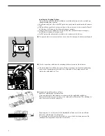
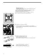
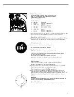
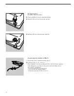
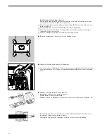
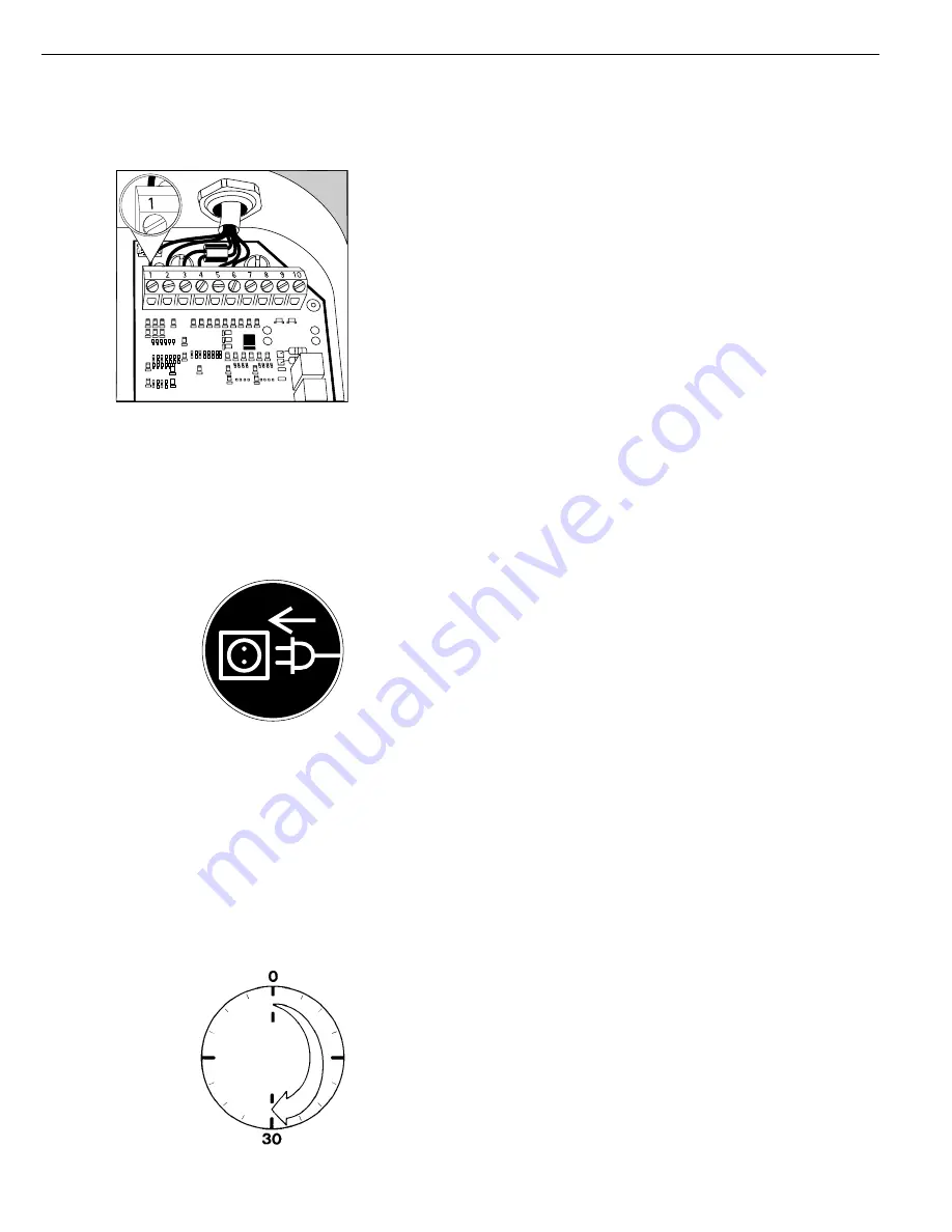
Connect the cable to the weighing platform as follows:
– Expose approximately 5 cm (2 inches) of the isolated wires for installation.
– Remove the casing from approximately 1 cm (1/2 inch) of the wires and attach ferrules to
the wire ends.
– Fit the ferrite ferrule over all wires.
– Attach the wires securely to the screw terminals.
Pin Assignments:
No.
Signal name
Meaning
1
BR_POS
Bridge supply voltage (+)
2
SENSE_POS
Sense (+)
Bridge supply voltage
3
OUT_POS
Measuring voltage positive
4
OUT_NEG
Measuring voltage negative
5
SENSE_NEG
Sense (–)
Bridge supply voltage
6
BR_NEG
Bridge supply voltage (–)
!
Please refer to the data sheet or operating instructions for the load cell or weighing plat-
form in question for details on the assignment of wire colors to signals.
Isolate any lines that are not used.
Weighing platforms with 4-conductor technology:
!
If a load receptor that uses 4-conductor technology is connected, connect wire 1
(BR_POS) to wire 2 (SENSE_POS) and wire 6 (BR_NEG) to wire 5 (SENSE_NEG).
Connecting the Combics to AC Power
§
Check the voltage rating and the plug design.
$
The indicator is powered by an external power supply.
§
Use only original Sartorius power supplies:
– YPS02-X.. for use within the hazardous area.
– YPS02-XV24 24V industrial power module for use within the hazardous area.
Note: Install both cables so that they are stationary
(Devices suitable for flexible cable installation available on request.)
– YPS02-Z.. for use outside the hazardous area.
Connecting the External Rechargeable Battery Pack
– The model YRB02-X external explosion-protected rechargeable battery pack can be
installed within the hazardous area.
Connecting Electronic Peripheral Devices
§
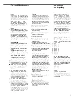
Make absolutely sure to unplug the indicator from AC power before you connect or dis-
connect a peripheral device (printer or PC) to or from the interface port.
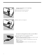
Grounding (Earthing) Using an Equipotential Bonding Conductor
§
Connect the CIXS using a grounding cable (equipotential bonding conductor not part of
the equipment supplied) to the main grounding terminal. In addition, the metal housing
of the power supply is grounded by the protective grounding conductor of the power
cable. The metal housing of the weighing platform is connected to the braided shield of
the AC adapter (power supply).
Warmup Time
To ensure accurate results, the indicator must warm up for 30 minutes before operation.
Only after this time will the indicator have reached the required operating temperature.
Using Equipment Verified as Legal Measuring Instruments in the EU*
$
Make sure to allow the equipment to warm up for at least 24 hours after initial connec-
tion to AC power or after a relatively long power outage.
* including the Signatories of the Agreement on the European Economic Area
7


