Analog/Digital Converter
(ADC)
Purpose
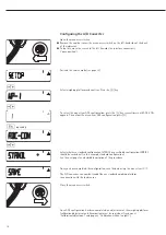
Adjust the parameters of the
analog/digital converter to the connect-
ed load cell or weighing platform.
After ADC configuration the ADC is
defined as a scale in connection with
the load sensor.
Set-up Information
– ADC configuration is only possible
when the menu access switch is open.
Close the menu access switch after ADC
configuration, as otherwise there will
not be any display of the conditions
“overload” (“H”) and “underload” (“L”).
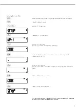
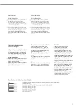
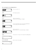
– When the service mode is active, the
ADC configuration takes place in the
Setup menu under “WP-1” under the
menu item ADC-CON.
– Enter the maximum capacities in a suit-
able weight unit, without any decimal
places (decimal places will be truncated
by the rounding function).
!
If you return to the highest level of the
menu without saving the configuration
parameter beforehand (menu item save)
any settings that have been made will
be deleted.
– Entries made in the ADC configuration
will not be affected by a menu reset
(returning the set-up parameters to
their factory settings).
!
Note:
Once the A/D converter configuration
has been locked, the indicator can no
longer be used to influence weighing
results. The scope of functions available
in the weighing instrument is defined
by the A/D converter. Weighing func-
tions that can be activated include
reading weight values, taring, calibra-
tion, reading the tare value,
saving/deleting the tare entry
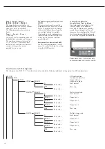
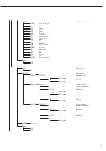
Description of the Individual Menu
Items for the A/C Converter
Configuration
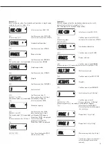
Standard or verifiable configuration
(menu items STAND. / VERIF.)
In ADC configuration it is first selected,
whether the weighing platform should
be configured as a standard or verifi-
able (for use in legal metrology) weigh-
ing platform.
– Standard configuration (STAND.)
– Verifiable configuration (VERIF.).
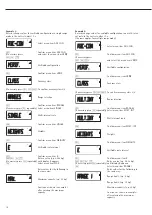
Accuracy Class (menu item CLASS)
Only displayed in verifiable configura-
tion.
Only menu items 3/4 (accuracy class
l/m) can be selected. If the menu item is
not already marked as being active with
a circle (o), the ) key must be pressed
once to activate it.
Range Selection (menu item RANGES)
Depending on the setting under this
menu item, the menu points RANGE 1,
RANGE 2 and RANGE 3 will either be
displayed or will not be displayed for
further configurations.
– Single range mode (SINGLE)
The entire weighing capacity is divided
into decimal numbers dependent on the
smallest scale interval d and the maxi-
mum weight. The readability corre-
sponds to the scale interval d.
– Multi-interval scale (MULT.INT.)
The function “multi-interval scale”
divides the weighing capacity into a
maximum of three intervals with differ-
ing readability. The corresponding
change takes place automatically at the
defined interval limits. After taring, the
best possible resolution (smallest scale
intervals) is available even when there is
a load on the weighing platform.
– Multiple range mode (MULT.R.)
A multiple-range scale has two or three
weighing ranges. When the range limit
for the lower weighing range is exceed-
ed, the scale switches into the next
highest weighing range (lower resolu-
tion). The scale only switches back to
the higher resolution when the weigh-
ing platform has been completely
unloaded.
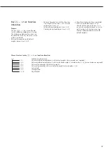
Scale Interval d
The scale interval d indicates the reso-
lution of the weighing instrument.
The scale interval can only be entered
in increments of 1, 2, 5, 10, 20, etc.
When “verifiable configuration” is used,
this menu item is not displayed.
When using verifiable or verified weigh-
ing platforms (classes l and m), the
scale interval d is the same as the
verification scale interval e.
Verification Scale Interval e
The verification scale interval e indi-
cates the resolution of the weighing
instrument in legal metrology. The scale
interval can only be entered in incre-
ments of 1, 2, 5, 10, 20, etc.
When “standard configuration” is used,
this menu item is not displayed.
Maximum Capacity (max. cap.)
The maximum capacity is the maximum
load that may be placed on the weigh-
ing platform. When heavier weights are
used the weighing instrument displays
overload “H”.
The scale intervals of the weighing
instrument are calculated using the
maximum capacity and the scale inter-
val d (e.g. max. capacity = 15.000 kg,
smallest scale interval = 0.005 kg yields
3000 scale intervals).
In legal metrology the total number of
intervals must be no more than 3125 e,
and when using multi-interval scales
there must not be more than 3125 e
intervals per range.
9
Summary of Contents for Midrics 1
Page 1: ...Operating Instructions Sartorius Midrics 1 Midrics 2 Models MIS1 MIS2 Indicators 98648 014 89 ...
Page 92: ...92 Dimensions Scale Drawings All dimensions given in millimeters 92 ...
Page 97: ...97 C ...
Page 98: ...98 ...
Page 99: ...99 ...
Page 100: ...100 ...
Page 101: ...101 ...
Page 102: ...102 ...
Page 104: ...104 ...


