background image

SARTORIUS PMA 7500...

7

Calibrating/Adjusting the Scale

Calibration/Adjustment Sequence

Check and, if necessary, adjust the following factors:

1. Zero-point offset value
2. Off-center load
3. Linearity
4. Span adjustment

Zero-Point Offset Value

The zero-point offset value is necessary for adapting the bridge voltage of the
strain-gauge load cell to the operating range of the scale electronics.
This may be necessary:

– after replacing the strain-gauge system
– after replacing the main PCB
– if the span cannot be adjusted (even with the service software) and the

error code “

E  02

” is displayed

– when the zero-point offset voltage has changed and is outside the

tolerance limit (e.g., due to the strain-gauge load cell being “bent”)

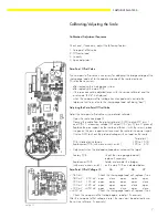
Adjusting the Zero-Point Offset Value

Adjust the zero-point offset value using a digital voltmeter.

– Open the scale (see page9)
– Connect the cable from the digital voltmeter (DVM) to plug ST2, pins 1

and 2 (Pin 1: measuring voltage (OP output IC6 / pin 6), pin 2: ground)

– Replace the pan support on the scale and fasten it with the screws, place

the pan on the pan support and re-connect the scale to the power supply

– Use the DVM to check the preload voltage with no load on the scale:

Target (mV)

PCB installed at the factory

-120 to -1,600

Replacement PCB (with menu access switch):

-120 to    -350

– Adjustment when the preload voltage does not equal the target:

Factory PCB:

   Check the strain-gauge load cell;
   replace if necessary

Replacement PCB

   Solder or de-solder the bridges

(with menu access switch):    on the main PCB as indicated below

Zero-Point Offset Voltage J5

J6

J7

J8

J9

< -580 mV

Check the strain-gauge load cell; replace if nec.

-580 mV ... -350 mV

open

close

open

open

open

-350 mV ... -100 mV

open

open

open

open

close

-100 mV ...+120 mV

open

open

open

close

open

+120 mV ...+360 mV

open

open

close

open

close

> +360 mV

Check the strain-gauge load cell; replace if nec.

– Check the zero-point offset voltage again; re-adjust if necessary
After the zero-point offset voltage is reset, the span must be adjusted (using
the service software, if necessary).

Nullp-d.TIF

Summary of Contents for PMA7500D-X

Page 1: ...WPM5003 e98061 Sartorius PMA7500 Electronic Paint Mixing Scales Service Manual for PMA7500 Models incl Spare Parts List and Service Specifications Sartorius AG Weighing Technology F...

Page 2: ......

Page 3: ...ng the Scale Operating Menu with or without Storing the New Settings 6 Activating the BPI Mode 6 Calibrating Adjusting the Scale 7 Calibration Adjustment Sequence 7 Zero Point Offset Value 7 Off Cente...

Page 4: ...PMA7500 X PMA7500 X00AM PMA7500 X00C PMA7500 X00W PMA7500D PMA7500D 000AM PMA7500D 000C PMA7500D 000W PMA7500D X PMA7500D X00AM PMA7500D X00C PMA7500D X00W PMA7500D X00CV1 USA Differences to former PM...

Page 5: ...code 8 1 2 If menu access is blocked this is indicated by a minus sign preceding the menu code number e g 1 1 1 1 1 rather than 1 1 1 1 1 To make the menu accessible select the menu code 8 1 1 the onl...

Page 6: ...ment error is 2 or replacing the main PCB Important After working in the BPI mode make sure to set the write protect again using the Close function so that the scale returns to the standard data trans...

Page 7: ...in 1 measuring voltage OP output IC6 pin 6 pin 2 ground Replace the pan support on the scale and fasten it with the screws place the pan on the pan support and re connect the scale to the power supply...

Page 8: ...lign the pan support arms approximately with the off center load bolts and place the pan on the pan support Check the off center load see Checking the Off Center Load above and adjust if necessary Lin...

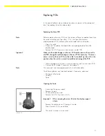
Page 9: ...he old PCB change the solder bridges on the new PCB if necessary The menu access switch on the new PCB must be in the accessible position this is the position when the switch is moved toward the outer...

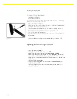
Page 10: ...head together with the connecting cable can be removed Follow the above instructions in reverse order to install the new PCB Replacing the Strain Gauge Load Cell Open the scale see page 9 Unplug the...

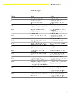
Page 11: ...data stored in the 2nd tare memory memory E 11 Value cannot be stored in the Press 2nd tare memory E 22 Weight too light or no load Increase the weight on the scale on the scale E 30 p key pressed wh...

Page 12: ...idual values 5 Interface 5 1 Baud rate 5 1 1 150 baud 5 1 2 300 baud 5 1 3 600 baud 5 1 4 1 200 baud 5 1 5 2 400 baud 5 1 6 4 800 baud 5 1 7 9 600 baud 5 2 Parity 5 2 1 Mark 5 2 2 Space 5 2 3 Odd 5 2...

Page 13: ...ance ppm K PMA 7500 7500 g 0 1 g 5000 g 0 1 g 5000 g 0 6 g 10 PMA7500D 999 95 7500 g 0 05 0 1 g 5000 g 0 1 g 5000 g 0 1 g 10 Span Linearity Model Class Adjustm weight Test weight Permissible Tolerance...

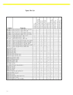
Page 14: ...South Afrika 1 1 1 6971411 Power supply STNG 6 240V Australien 1 1 1 6971412 Power supply STNG 6 Europa 230V 1 1 1 6971413 Power supply STNG 6 USA CDN 120V 1 1 1 6971414 Power supply STNG 6 240V GB 1...

Page 15: ...SARTORIUS PMA 7500 15...

Page 16: ...ns without the prior written permission of Sartorius AG The status of the information specifications and illustrations in this manual is indicated by the date given below Sartorius AG reserves the rig...

Reviews: