16
2.
Adjustment using the PSION server
– Switch the scale to the BPI mode (see page 11).
– Switch on the PSION server and call the CAS program (version 4.4 or
newer)
– Select the menu item “Electr-zero-point” from the “Diagnosis” submenu
– With no load on the weighing pan, a value of 14.8 % ±11% should
appear in the PSION display.
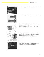
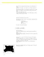
If the value displayed is outside the tolerance limits, you can adjust this
voltage by changing the solder bridges LB7 and LB8.
LB7
LB7/LB8
LB8
LB7/LB8
Zerp Point Offset Value
1 / 2
1 / 1
1 / 2
2 / 2
< 25,8 %
open
close
open
open
> 3,8 %
close
open
close
open
After adjusting the zero point offset, proceed with the adjustment of the span
(sesitivity) (with the PSION server, if desired).
Adjusting the Linearity
Note:
There are two methods for adjusting the linearity:
1. As described in this manual, or
2. Using the MC1 PSION server
– Test the linearity of the scale in 1000g steps over the entire weighing
range.
– If any deviation is greater than the tolerance values given, you need to
adjust the linearity.
– Set the code “1 9 5” in the scale operating menu (external
linearization accessible).
– When 0.0g is displayed, press the
e
key and hold it for about 3
seconds; then release it.
– The first linearization value is displayed.
– Place the prompted weight on the middle of the weighing pan.
– After the weight is stored, the next weight value is displayed.
– Each linearity support point is called and stored.
– When this routine ends, the scale returns to the normal operating mode.
– If desired, reset the menu item “1 9 “ to the standard setting.
Note:
After linearization, make sure you perform the adjustment of the span
(sensitivity).
Summary of Contents for QC34EDE-S
Page 2: ...2...


