background image

59

Service Manual Signum

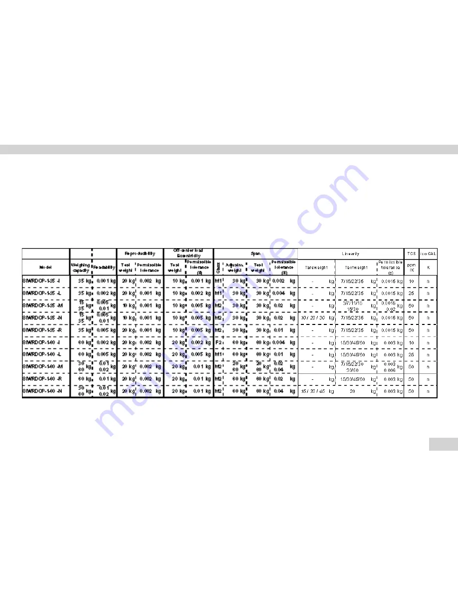
Calibration/Adjustment Data

Calibration/Adjustment Data for the SIWR

Example for the order number of a Signum full range scale: 

SIWRDCP-2-60-R oder  SIWRDCP-3-60-RCE 

Model type   | Sensor         |  Platform        |  Type of/      |   Application- |  

Capacity  | 

Display         |  Verifiable/ |


technology 

dimensions 

material 

level 

(kg) 

resolution  

verified


(in mm) 


versions

 SIW 

R

 1)


DC 

P

 4)


15 

RCE


 1)

 = SIWR: „Regular“ standard weighing system - (strain gauge technology)   

4)

 = Painted

just_Signum_290508.xls

Summary of Contents for Signum 1

Page 1: ...WSI5007 e12036 Service Manual Sartorius Signum 1 Signum 2 Signum 3 Models SIWR SIWA SIWS Signum Series Complete Scales ...

Page 2: ...le Featuring Electromagnetic Force Compensation 14 Activating the Service Mode 15 Activating the Service Mode 15 Additional Menus in the Service Mode 17 In the Text Menu Setup 17 Calibration Adjustment Functions 19 1 9 1External Calibration Adjustment with Default Weights 19 1 9 3External Calibration Adjustment with User Defined Weights 20 1 9 4Calibration Adjustment with an Internal Weight 2 22 1...

Page 3: ...ystem PCB 43 Replacing Comonents of SIWAEDG 44 Optional Data Output Ports Interfaces 46 Installation of the Profibus Module 46 Data Output Plate with IP44 Protection 47 Data Output Plate with IP65 Protection 48 COM 1 Port SIWAEDG 49 Error Codes 50 Additional Tools Programs etc 52 Block Diagram 53 Working with the Service Software 54 Service Switches 54 Function of the Service Switches 54 Menu Acce...

Page 4: ...tion and adjustment of Signum series scales as well as on error messages If you have any comments or require more detailed information please write to us at Int Service Sartorius com Printing the Manual To save paper we recommend configuring the printer settings in the Adobe Acrobat program as follows File Print Properties Layout Pages per Sheet 2 ...

Page 5: ... used in this manual Warning Indicates safety instructions Please make sure to observe these instructions otherwise physical injury or material damage may result Note The light bulb symbol indicates important information that will help prevent errors as well as other useful tips ...

Page 6: ...eatening injuries To avoid electric shock always disconnect the power cord from the wall outlet mains supply before beginning repair work or replacement of components When the scale housing is open always use an isolating transformer or a ground fault circuit interrupter Make sure no voltage is present in the scale before connecting or disconnecting any cables to or from it Otherwise assemblies or...

Page 7: ...s not available in an explosion protected version at this stage P Material at the initial stage only painted but will also be available in stainless steel at a later time Resolutions R 6 000d 15 000d L 15 000d I 30 000d N multirange n 3 000d M multiintervall n 3 000d S 50 000d S 100 000 d H 100 000d D Dual range high resolution 50 000 P Polyrange high resolution 50 000 K Dual range low resolution ...

Page 8: ...ominal load 20kg 50kg 100kg Design 2 Advanced weighing system Strain gauge technology to the right Without built in motorized calibration weight Nominal load 20kg 50kg 100kg SIWAEDG weight Nominal load 16kg 35kg 65kg Design 3 Supreme weighing system Narrow forked lever system to the right With built in motorized calibration weight Nominal load 20kg AUT22923a JPG PW_Sys_DMS_01 eps AUT22925a JPG PW_...

Page 9: ...r system to the right With built in motorized calibration weight Nominal load 40kg Design 5 Regular weighing system Strain gauge technology to the right Without built in motorized calibration weight PW15 EX Nominal load up to 30kg Design 6 Regular weighing system Strain gauge technology to the right Without built in motorized calibration weight PW10 EX Nominal load up to 100kg ...

Page 10: ...32 connection cable 25 pin 9 pin 7357314 Torx screwdriver set 10 15 20 Accompanying Literature Designation Order No Operating instructions WSI6007 e07074 Service manuals spare parts lists etc can be downloaded from the Internet at http iss sartoserver de Registration is required please contact Malte Pramann Sartorius com for details http iss sartoserver de hinterlegt ...

Page 11: ...f the Equipment Display Units Flat Screen Display Unit These are available with various screen types The display unit can be hung on the load cell or secured to the scale using a stand or column Tall Display Unit This is available as an option with an A D converter or a rechargeable battery pack Position Description ...

Page 12: ...GMP footer Press and hold 2 seconds Signum 3 only I To toggle the scale to Info mode Signum 3 only d Identifiertaste zur Eingabe von Bediener kennungen Signum 2 and 3 only K Toggle unit between normal and 10 fold higher resolution Signum 2 and 3 only L Netto Bruttowert Taste Nur Signum 2 und 3 w Toggle between display modes within an application program Signum 2 and 3 only r Lets you modify refere...

Page 13: ...stalled as optional equipment C Main PCB D Strain gauge technology system PCB E Various versions of the strain gauge system F Standard housing G Without built in motorized internal calibration weight This cable is suitable only for the Ethernet and Profibus options AUT24188 JPG A B C AUT24197 JPG System cable Cable to main PCB D Cable to power supply Data output cable Cable to the system PCB Stand...

Page 14: ...interfaces can be installed as optional equipment C Main PCB D Electromagnetic force compensation system PCB E Various versions of the electromagnetic force compensation system F Standard housing G Built in motorized internal calibration weight AUT24252 JPG AUT24188a JPG A B C D G E F A C B Cable to power supply Data output cable Cable to system PCB Optional RS232 or RS485 422 data interfaces 4 20...

Page 15: ...tion to set or clear a preload or to enter the date of service Switch the Signum scale off press the e Switch the Signum scale back on press the e While all segments are displayed briefly press the key APPL is displayed Using the k key scroll to SETUP Press the key WP 1 is displayed Using the k key scroll to CODE disp_wp 1_d eps disp_8888_d eps disp_appl_d eps disp_setup_d eps disp_wp 1_d eps ...

Page 16: ...Once you have entered the last number press the and keys in this order to activate the service mode An S in the upper right hand corner indicates that the service mode is active If you wish to exit the service code entry mode continue pressing the key until CODE reappears on the display Please note The only way to deactivate the service mode is to switch the scale off and then on again Important n...

Page 17: ...ollowing possible settings for configuring weighing platforms WP 1 WP 1 and WP2 WP 2 1 9 Calibration adjustment functions 1 9 1 Ext calibration adjustment with a default weight service mode not required 1 9 3 Ext calibration adjustment with a user defined weight service mode not required 1 9 4 Int calibration adjustment service mode not required 1 9 6 1 Internal linearization only for WP 2 on COM1...

Page 18: ...tion with automatic adjustment 1 10 2 3 Calibration with manual adjustment 1 18 Entry of calibration and linearization weights 1 18 1 Ext calibration weight of the user special value entry e g 10 000kg 1 18 2 1 Entry of linearization weight 1 1 18 3 1 Entry of linearization weight 2 1 18 4 1 Entry of linearization weight 3 1 18 5 1 Entry of linearization weight 4 1 Only accessible in the service m...

Page 19: ...tivate the service mode see page 15 1 9 1 External Calibration Adjustment with Default Weights Select weighing platform WP 1 Press the key to access the number menu Select menu 1 9 1 External calibration adjustment with default weight by pressing the k key repeatedly and then pressing the key briefly to confirm If this menu has already been selected switch the indicator off and then on again to ex...

Page 20: ...tween the current value and the value from the last adjustment calibration procedure is displayed To interrupt the calibration adjustment procedure press the key Press the J key to calibrate adjust the scale and display the value if menu 1 10 2 has been selected 1 9 3 External Calibration Adjustment with User Defined Weights Select weighing platform WP 1 Press the key to access the number menu 3 O...

Page 21: ... EXT USE is displayed Press the J key to continue the calibration adjustment routine After approx 2 seconds the required calibration weight user defined weight is shown in the display Place the required weight on the scale After a brief pause the difference between the current value and the value from the last adjustment calibration procedure is displayed To interrupt the calibration adjustment pr...

Page 22: ...ng the display of the scale press and hold the J key until C INTERN is displayed Press the J key to continue the calibration adjustment routine The motorized internal calibration weight is placed on the scale and then removed After approx 2 seconds the difference in the current calibration value is displayed Press the J key to store the current calibration weight Afterwards the scale returns to th...

Page 23: ...t menu code 1 9 6 Ext Linearization with Default Weight Then briefly press the key to confirm Press and hold the key to store the selected menu and return the scale to the weighing mode If this menu has already been selected switch the indicator off and on again to exit the service mode After taring or zeroing the display of the scale press the J key until L EXT DEF is displayed display_serv_01 ep...

Page 24: ...nd required weight is displayed Place the required weight on the scale After a brief pause the difference between the current value and the value from the last adjustment calibration procedure is displayed Press the J key to store the 2nd linearization weight Now the 3rd required weight is displayed Place the required weight on the scale After a brief pause the difference between the current value...

Page 25: ...e from the last adjustment calibration procedure is displayed Press the J key to store the 4th linearization weight The scale now prompts a zero point remove all weights from the scale Once the zero point is stored the scale will automatically return to the weighing mode Weights displayed depend on the scale model 3 Only displayed if menu code 1 10 2 Calibration with manual adjustment has been sel...

Page 26: ... menu code 1 9 7 Ext linearization with user defined weight and confirm by briefly pressing the key To store the selected menu press and hold the key The scale now returns to the weighing mode If this menu has already been selected switch the indicator off and on again to exit the service mode After taring or zeroing the display of the scale press the J key until L EXT USE is displayed display_ser...

Page 27: ...weight Next the 2nd required weight is displayed After a brief pause the difference between the current value and the value from the last adjustment calibration procedure is displayed Press the J key to store the 2nd linearization weight Now the 3rd required weight is displayed After a brief pause the difference between the current value and the value from the last adjustment calibration procedure...

Page 28: ...splayed Press the J key to store the 4th linearization weight The scale now prompts a zero point remove all weights from the scale Once the zero point is stored the scale will automatically return to the weighing mode Weights displayed depend on the scale model 3 Only displayed if menu code 1 10 2 Calibration with manual adjustment has been selected 1 9 8 Setting the Preload 10kg eps display_serv_...

Page 29: ...he number menu Select menu 1 9 8 Setting the preload by pressing the k key repeatedly and then pressing the key briefly to confirm Press and hold the key to store the selected menu and return the scale to the weighing mode Tare the scale by pressing the key or zero the display by pressing the key After the scale has been tared NET might remain in the display Place the preload weight on the scale P...

Page 30: ...ge 19 for more information Activate the service mode see page 15 Select the weighing platform WP Press the key to access the number menu Select menu 1 9 9 Clear preload by pressing the k key repeatedly and then pressing the key briefly to confirm Press and hold the key to store the selected menu and return the scale to the weighing mode Remove the preload weight from the scale A weight with a prec...

Page 31: ...nual Signum Working with the Service Mode Press the J key until CLr Vor is displayed Press the key The preload is cleared and after a brief pause the scale returns to the weighing mode Clr_vor eps 0kg eps vorl4 eps ...

Page 32: ...nu Select menu code 1 18 1 Ext user defined calibration weight by pressing the key and the k key repeatedly Access the input mode for the user defined weight by briefly pressing the key The first number blinks Enter the user defined weight 10 000 kg in this example press the following keys in order k p k Now the last number entered blinks Press the key again to store the user defined weight displa...

Page 33: ...eys in the order indicated 3 k p 6 k k k Now the last number entered blinks Press the J key to store the 1st linearization weight Then the scale returns to menu code setting 1 18 2 Using the k key scroll to the menu code settings 1 18 3 1 18 4 and 1 18 5 and enter the values for Lin 2 Lin 3 and Lin 4 according to the instructions above If you do not require all linearity positions enter 0 in the u...

Page 34: ...hrough the warranty stickers seals 3 Open the housing 4 Now all parts are accessible Closing the Display Unit 1 Plug all connectors back into the unit 2 Close the display unit 3 Reconnect the unit to line voltage 4 Check the functions of the display unit to ensure that they are working properly Important note Once the scale has been repaired and checked to ensure its proper functioning new warrant...

Page 35: ...eft Open the display unit see page 34 Replace the entire front panel with a new one Close the display unit see page 34 Replacing the Cable Open the display unit see page 34 Unplug all connectors from the cable Loosen the screw Replace the cable with a new one Close the display unit see page 34 After replacing the cable use a torque wrench to tighten the cable gland to 3 Nm AUT23152 JPG AUT23301a J...

Page 36: ...omponents could be destroyed Open the display unit see page 34 Unplug the cable from the ST1 connector and the overlay cable from the keypad If an A D converter or rechargeable battery pack is being used unplug the cable from connector ST2 also Remove the screws Remove the display PCB X Replace the display PCB with a new one Connect the cable Close the display unit see page 34 AUT24201 JPG AUT2420...

Page 37: ...upport plate 3 Remove the four screws R from the O ring see picture on the right 4 Remove the ten screws P from the cover Cut through the warranty stickers seals Remove the O ring on units with IP65 protection 5 The scale housing is now accessible 6 Remove the six screws O from the data output plate U Remove the gasket on units with IP65 protection 1 2 4 5 6 O P Q Explo00a jpg Explo01z jpg Explo01...

Page 38: ...power source 1 Remove the load cell plate 2 Loosen the two screws Q on the load cell and remove the load cell 3 Place the load cell to the side see picture on the right 4 Remove the ten screws P from the cover 5 Cut through the warranty stickers seals 6 The scale housing is now accessible AUT24260a JPG AUT24261 JPG AUT24252 JPG Q P AUT24262 JPG ...

Page 39: ...sing in order 3 If necessary be sure to include the all O rings and gaskets 4 Replace and tighten the screws P 5 Plug the unit back into AC power 6 Check the scale to ensure that it is functioning properly Important note Once the scale has been repaired and checked to ensure its proper functioning new warranty stickers seals must be applied ...

Page 40: ...output plate U Cut through the warranty stickers seals Fold down the data output plate U Pry the protective cap A1 from the power PCB B1 To do this insert the end of a slotted head screwdriver into each of the four openings on the protective cap and carefully push the retainer clips located further down to one side Remove the protective cap A1 and disconnect the wire red brown Unplug connector X r...

Page 41: ... power cable from the wall socket mains supply first Otherwise components could be destroyed Different versions of this PCB see pages 59 60 can be installed in the unit Loosen and remove six screws O from the data output plate U Cut through the warranty stickers seals Remove the data output plate U When you replace the data output PCB Z make sure that the connectors are plugged in correctly If you...

Page 42: ...nnect the power cable from the wall socket mains supply first Otherwise components could be destroyed Different versions of this PCB see picture on the left can be installed in the unit Loosen and remove six screws O from the data output plate U Cut through the warranty stickers seals Remove the data output plate U When you replace the digital PCB be sure that all cables are reconnected AUT23155a ...

Page 43: ...ale Featuring Strain Gauge Technology Strain gauge scale with system PCB When you replace the system PCB make sure that all cables have been reconnected Important note See page 38 Opening a Scale Featuring Electromagnetic Force Compensation Electromagnetic force compensation scale with system PCB When you replace the system PCB make sure that all cables have been reconnected ...

Page 44: ...ective cover and carefully press the clips located at the bottom to the side Remove the protective cover and disconnect the power cord on the right blue brown Remove the left plug red blue remove the screws and replace the power supply Do not forget to reattach the protective cover Replacing the Main PCB Loosen and remove the ribbon cable and power supply cable Remove the screws cable and replace ...

Page 45: ...e screws and replace the PCB Check to make sure that the plug connections are connected properly after replacement Replacing the Data Output PCB Remove the screws cable and replace the PCB Once the data output PCB has been replaced make sure that the plug connections are properly connected If the battery is being replaced make sure that the polarity is correct ...

Page 46: ...5 Protection Important note After installation of the Profibus module the cable connectors must be equipped with a flat ferrite and glued with silicone see pictures on the rigth Data Output Plate with IP65 Protection DSC03656a JPG DSC03654a JPG AUT23155a JPG Bu1a DSC03658 JPG DSC03653a JPG DSC03651a JPG Bu2a St2a St1a FF FF SI SI ...

Page 47: ...ts Interfaces Data Output Plate with IP44 Protection Com1 RS232 Com1 RS232 Option COM2 Com1 RS232 Com1 RS232 Option COM2 Com1 RS232 Com1 RS232 Option COM2 Option Clock Com1 RS232 Com1 RS232 Option COM2 Com1 RS232 Option COM2 Option Clock PS 2 Ethernet ...

Page 48: ...um Optional Data Output Ports Interfaces Data Output Plate with IP65 Protection Com1 RS232 Com1 RS232 Option COM2 Com1 RS232 Com1 RS232 Option COM2 Com1 RS232 Com1 RS232 Option COM2 nicht benutzt nicht benutzt nicht benutzt ...

Page 49: ...apterkabel benötigt das die Verbingung zu nalen TxD RxD CTS DTR und GND ermöglicht Zum Progammieren müssen diese Signale zu sprechenden Gegenstellen einer RS232 Schnittstelle eines PCs geführtwerden Zum Testen TxD mit RxD und DTR mit CTS verbunden werden Schnittstelle Belegung der Schraubklemmverbinder Anschluss Funktion Anschluss Funktion 1 CTS 11 LOAD PRINTE 2 DTR 12 RESET_OUT 3 RXD 13 GND 4 TXD...

Page 50: ...ff and then on again If Err 340 is still displayed contact your local Sartorius Service Center Err 341 Data lost from RAM Leave the scale power on for at least 10 hrs battery needs to be recharged Err 343 Data lost from the memory module Contact your local Sartorius Service Center for transaction numbers in external alibi memory Inf 01 Data output not compatible with output format Change the menu ...

Page 51: ...fore taring Inf 22 Error in storing reference value load is too light Put a heavier weight on the scale Inf 23 Error in initializing an application Contact your local Sartorius Service Center Inf 29 Minimum load not reached Change menu or perform Close function check the interface and cable of the connected devicen Contact your local Sartorius Service Center Inf 30 31 Indicator is in the xBPI mode...

Page 52: ...hing platform connected Connect weighing platform NO WP No weighing platform connected Connect weighing platform In addition to standard tools you will need the following special tools and programs to work on Signum series scales Designation Order No Sartorius Service Software H8S 6740 88 with USB dongle Sartorius Service Software H8S 6740 89 with LPT dongle Registration in ISSS required ...

Page 53: ...53 Service Manual Signum Block Diagram Block Diagram ...

Page 54: ...switches Menu access switch L Flash switch M see page 20 for details Function of the Service Switches Menu Access Switch Warning Only open this switch for service purposes At all other times it should remain in the closed position This switch must be open in order to work with the Sartorius Service Software If the switch remains closed the error message ACCESS SWITCH LOCKED will be displayed in th...

Page 55: ...the PCB is ready to boot reload the application software using PPLOADER SBI XBPI Important note The COM 1 interface must be set to XBPI eXtended Binary Processor Interface protocol before you can perform calibration adjustment procedures or program the scale using the Sartorius Service Software see page 22 Close Function After using the service software select the Close function to reactivate writ...

Page 56: ...djustment procedures or program the scale using the service software Switch the Signum scale off press the e key Switch the Signum scale back on by pressing the e key While all segments are displayed briefly press the key APPL appears in the display Using the k key scroll to SETUP Press the key WP 1 is displayed disp_wp 1_d eps disp_8888_d eps disp_appl_d eps disp_setup_d eps ...

Page 57: ...der Taste k bis COM 1 scrollen Use the k key to scroll to COM 1 Press the key DATPROT is displayed Press the key again BPI 232 appears in the display Important note The X is not displayed when BPI 232 is selected disp_xbpi_d eps disp_com 1_d eps disp_datprot_d eps ...

Page 58: ...umber of a Signum full range scale SIWRDCP 1 15 L or SIWRDCP 3 15 NCE Model type Sensor Platform Type of Application Capacity Display Verifiable technology dimensions material level kg resolution verified in mm versions SIW R 1 DC P 4 1 15 N NCE 1 SIWR Regular standard weighing system strain gauge technology 4 Painted ...

Page 59: ...gnum full range scale SIWRDCP 2 60 R oder SIWRDCP 3 60 RCE Model type Sensor Platform Type of Application Capacity Display Verifiable technology dimensions material level kg resolution verified in mm versions SIW R 1 DC P 4 2 15 R RCE 1 SIWR Regular standard weighing system strain gauge technology 4 Painted just_Signum_290508 xls ...

Page 60: ...hnology dimensions material level kg resolution verified in mm versions SIW A 2 DC P 4 2 35 S 2 SIWA Advanced mechatronic weighing system strain gauge technology 4 Painted Signum SIWAEDG SIWAEDG 3 65 S 65 kg 1 g 20 kg 1 g 20 kg 2 g F2 20 kg 20 kg 1 g kg 0 Max kg 3 g 8 n SIWAEDG 3 35 S 35 kg 0 5 g 10 kg 0 5 g 10 kg 2 g F2 10 kg 10 kg 0 5 g kg 0 Max kg 1 5 g 6 n SIWAEDG 3 16 S 16 kg 02 g 5kg 0 2 g 5...

Page 61: ...ber of a Signum full range scale SIWSDCP 3 16 H oder SIWSDCP 3 16 HCE Model type Sensor Platform Type of Application Capacity Display Verifiable technology dimensions material level kg resolution verified in mm versions SIW S 3 DC P 4 1 15 N NCE 3 SIWS Supreme monolithic weighing system 4 Painted just_Signum_290508 xls ...

Page 62: ...reprinted or translated in any form or by any means without the prior written permission of Sartorius The status of the information specifications and illustrations in this manual is indicated by the date given below Sartorius reserves the right to make changes to the technology features specifications and design of the equipment without notice Status March 2012 Sartorius Goettingen Germany Printe...

Reviews: