34
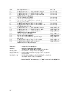
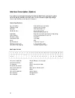
Pin Assignment for the Interface
Female Interface Connector:
25-position D-submini DB25S with screw lock hardware for the cable gland
Male Connector Required:
25-pin D-submini DB25S with integrated shielded cable clamp assembly (Amp type 826 982-1) and
fastening screws (male screws for female screw lock, Amp type 164 868-1)
Pin Assignment
Designations
Direction
Standard
Level
Pin 1: Protective
Ground
Pin
2:
Data Output (TxD)
Output
RS323
Pin
3:
Data lnput (RxD)
lnput
RS232
Pin 4: Not
Connected
Pin
5:
Clear to Send (CTS)
lnput
RS232
Pin 6: Not
Connected
Pin 7: Internal
Ground
Pin 8: Internal
Ground
Pin 9: Not
Connected
Pin 10: Not
Connected
Print/Tare*)
Pin
11:
+12 V
Output
(50 mA max.)
Pin
12:
Reset
—|
Output
TTL
Pin
13:
+5 V
Output
(50 mA max.)
Pin 14: Internal
Ground
Pin 15:
lnput
open
Collector
Pin 16: Low
Signal
Output
LS-TTL
Pin 17: OK
Signal
Output
LS-TTL
Pin 18: High
Signal
Output
LS-TTL
Pin 19: Set
Signal
Output
LS-TTL
Pin
20:
Data Terminal Ready (DTR)
Output
RS232
Pin 21: Not
Connected
Pin 22: Not
Connected
Pin 23: Not
Connected
Pin 24: Not
Connected
Pin
25:
+5 V
Output
(50 mA max.)
*) Print or tare (have this parameter implemented or changed by a Sartorius service technician)
Summary of Contents for TS 12
Page 39: ......

