background image

44 

VIS1X

 Operating Instructions


Accessing the Scale via the Network


t

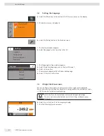
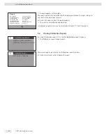
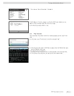
Go into the submenu “DHCP”.


t

Select “Off”.


t

Confirm with the 

l

 key.


y

The DHCP mode is now turned off.


t

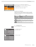
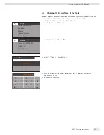
Go into the submenu “IP (xxxxxxx)“.


t

Select “

t

“ to enter a new IP address.


t

Enter a new IP address using the input box.
Make sure:


− to use an IP address from the same address space as the Windows PC 

(Subnet Mask).


− not to use the same IP address as the Windows PC.


t

Confirm the entry with the 

l

 button and exit the Settings menu.

The settings may have to be configured in the submenu “Subnet Mask” and 
“Gateway”.


t

Restart the scale.


t

Check the network connection (see Chapter 9.3, page 44). 

9.3  Testing the Network Connection

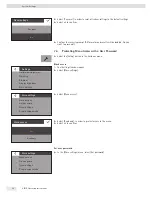
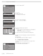
The IP address and device ID can always be found in the submenu “Device 
Information”. 


t

Press the 

i

 button to call up the “Settings” menu.


t

Go into the submenu “Device Information”.

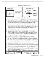
Ethernet

Device ID (0032602403)
DHCP (On)

IP (172.16.26.94)
Subnet mask (255.255.240.0)
Gateway (172.16.16.1)

DHCP

On

Off

IP

172.16.26.94

t

172.16

.000.000

1

4

7

0

2

5

8

3

6

9

.

C

Settings

Language
Date and time
Device information
Application
Calibration/Adjustment

Summary of Contents for VIS1X

Page 1: ...1000028871 Operating Instructions PMA Vision VIS1X VIS1X EU Paint mixing Scale for Use in Potentially Explosive Atmospheres of Class I Zone 1 and Class I Division 1...

Page 2: ......

Page 3: ...Symbols on the Device 13 4 Operating Concept 14 4 1 Operating and Display Elements in the Operating Display 14 4 2 Sartorius Menu 15 4 3 Scrolling in the Display 16 4 4 Entering Figures on the Number...

Page 4: ...3 2 Access via UPnP Universal Plug and Play 46 9 3 3 Web Browser Access 46 9 4 Changing the Device Name of the Scale 47 10 Cleaning and Maintenance 48 10 1 Cleaning 48 10 2 Servicing 48 11 Faults 49 1...

Page 5: ...p and is carried out by the operating engineer laboratory manager or the operator of the device Electrician A qualified electrician has the specialized training knowledge and experience as well as fam...

Page 6: ...er YCO16 Z installed outside of the potentially explosive area at all times using only the link cable supplied The scale can be used in potentially explosive areas in Zone 2 Appropriate containers mus...

Page 7: ...associated electrical apparatus that can only be installed outside of the potentially explosive area Please observe Certificates of Compliance 3055566 as well as Control Drawing 2028209 in Chapter 18...

Page 8: ...your fingertips Do not use parts of clothing e g sleeves or sponges for cleaning because these can scratch the surface e g due to rivets or buttons in the sleeve or sand in the sponge 2 6 Safety Devi...

Page 9: ...device for emergency switch off t t Immediately disconnect the damaged device from the power t t Have any malfunctions repaired immediately by Sartorius Service 2 11 Personal Protective Equipment Pers...

Page 10: ...lastic casing The YPS07 USB power supply for the ex link converter may only be connected to supply voltages of min 90 V and max 264 V at a frequency of 48 62 Hz Observe connection data see Chapter 15...

Page 11: ...X Operating Instructions 11 Device Description 3 Device Description 3 1 Device Overview 3 2 1 Fig 1 Scale front view No Name 1 Operating display see also Chapter 4 1 page 14 2 Support column 3 Weighin...

Page 12: ...e ex link converter No Name 1 RJ 45 socket for link cable 2 Cable holders 3 Support column 4 Link cable blue 5 Ex link converter 6 Anti theft locking device 7 Grounding terminal for equipotential bond...

Page 13: ...power supply 3 2 Symbols on the Device Seal on Scales Verified for Use in Legal Metrology Legislation requires that a seal be affixed to verified scales On Sartorius devices this seal takes the form o...

Page 14: ...fo for minimum capacity Min and the verification scale interval e appear on verified scales 3 In verified mode for devices where e does not equal d The frame indicates a scale interval 4 Current weigh...

Page 15: ...cription 1 Access a formula access the formula list 2 Mixing without formula weighing function 3 Connection status Displays the connection status Error Ethernet cable not connected No connection Estab...

Page 16: ...g a gray scroll bar appears on the right of the display indicating where you are in the list of options t t Tap the desired entry to select it 4 4 Entering Figures on the Number Pad You can enter nume...

Page 17: ...switch the keyboard display from numbers to letters t t Use the back arrow key to delete the last character t t The l key ends the process and saves character input 4 6 Key Fadeout To prevent operatin...

Page 18: ...culation method when mixing without job REST protocol Selection of the REST protocol Battery backup There is an attempt to finish the mixing process after the power failure A result is generated No re...

Page 19: ...ce More Settings Menu access Setting access protection for the menu Set user password Setting user password Reset settings Resets all system settings to default settings Activate upload mode Activate...

Page 20: ...e right setup location Set up the device on a stable even surface that is not exposed to vibrations Maintain free access to the device at all times The devices must be handled carefully according to t...

Page 21: ...connected from the power supply for all assembly work Procedure t t Place the weighing pan onto the scale from above 5 5 Connecting the Scale Procedure t t Insert the link cable plug into the socket o...

Page 22: ...time Inspections should be carried out at least once every three years The applicable requirements and guidelines should also be observed during operation Establish a low resistance connection from t...

Page 23: ...customer supplied equipotential bonding conductor Connecting a PC Notebook t t Plug an Ethernet cable 1 into the Ex Link converter and connect the cable to a Windows PC direct connection or to a netwo...

Page 24: ...ight mains adapter for your mains power supply Mains adapter set YAK01 Bag Region Country a transparent Europe EU except United Kingdom b blue USA c yellow United Kingdom Mains adapter set YAK02 d red...

Page 25: ...en remove 2 the mains adapter Connection to Power Supply t t Insert a USB cable 2 into the ex link converter t t Insert the USB cable into the YPS07 USB power supply t t Plug the power supply into a w...

Page 26: ...sults are delivered the scale must warm up for at least 30 minutes after initial connection to the power supply Only then will the device have reached the required operating temperature Using a Scale...

Page 27: ...or by date t t Select the Sort button in the Sartorius menu y y The Sorting settings window appears Sorting alphabetically t t Select Line 1 in order to sort the formulas according to line 1 t t Selec...

Page 28: ...ion factor is reset 6 4 Mixing without Job t t Select the Mixing w o job button in the Sartorius menu 1 y y The Weighing application appears t t Remove the load from the scale t t Select 0 1 to zero t...

Page 29: ...lue The figure shows the display of the gross value G 1 t t Select G 1 in order to display the calculated value 6 4 3 Mixing a Formula with Factor Calculation The factor calculation enables you to wei...

Page 30: ...5 2 see Chapter 6 4 1 page 29 t t Select w 3 to start the formula t t Slowly add the first component 200 g of the formula until the display shows 200 o 1 t t Select Component takeover 2 Toggle betwee...

Page 31: ...d in but the container actually contains 150 g by weight in accordance with the factor you selected t t Select l to confirm 1 6 5 Data Input The data input formulas is carried out via Webservices see...

Page 32: ...las will not be deleted following the mixing process connection status hidden Off Formulas are deleted following the mixing process Mixing without job On Display Mixing without job in the Sartorius me...

Page 33: ...se The scale stability is displayed as soon as the weighing result is constant within a defined range Until stability is reached the measured value is shown in gray on the display and only turns black...

Page 34: ...urn to the menu 7 3 Weight Unit Conversion You can configure the weight unit and accuracy of the weight value displayed Access to convert the unit and the resolution is only possible if the calculatio...

Page 35: ...untry s laws regarding legal metrology and verification permit this Unit Factor Display Grams 1 00000000000 g Parts per pound 1 12876677120 p Some weight units and accuracy settings may be blocked fro...

Page 36: ...ess y y The Settings window opens t t Select More settings t t Select Menu access t t Select Read only in order to protect access to the menu t t Select l to confirm Set user password t t In the More...

Page 37: ...ctive once you have returned to the first level of the menu To change the password the old password must first be entered A new password can then be set To completely delete the password and allow acc...

Page 38: ...ieve the highest accuracy possible regularly calibrate and adjust the scale e g daily after switching on the scale each time the scale is leveled each time ambient conditions have changed temperature...

Page 39: ...tion weight on the weighing pan t t Place the calibration weight on the weighing pan y y Calibration starts automatically The calibration is performed CAL External Zero the scale G 0 4 g A START 1 CAL...

Page 40: ...libration Reports t t Select Calibration report 1 in the Calibration adjustment window y y The Calibration report window opens The current reports are listed in the Calibration report window t t Selec...

Page 41: ...gs menu t t Go into the submenu Ethernet If the display says DHCP On the settings are correct t t If not go into the submenu DHCP t t Select On t t Confirm with the l key y y The DHCP mode is now turn...

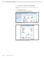
Page 42: ...The following settings must be made to connect the scale to a network with fixed IP addresses 9 2 1 Configuring Network on a PC t t Open the Network and Sharing Center on your Windows PC Start Contro...

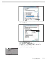
Page 43: ...t Select Use the following IP address 5 t t Enter the IP address of the network connection 6 t t Confirm your entry with OK and close the following window with OK 9 2 2 Configuring Network on the Scal...

Page 44: ...he l button and exit the Settings menu The settings may have to be configured in the submenu Subnet Mask and Gateway t t Restart the scale t t Check the network connection see Chapter 9 3 page 44 9 3...

Page 45: ...input area of the start menu enter the command cmd t t Enter the command ping in the Windows command console followed by a space and the IP address of the scale t t Confirm the entry with Enter y y T...

Page 46: ...her UPnP devices all of the PMA Vision scales located on the network are listed under Other Devices t t Call up the properties of PMA Vision PAINT by clicking with the right mouse button The device si...

Page 47: ...the Settings menu t t Go into the submenu Ethernet t t Go into the submenu Device ID t t Select t to enter a new device ID t t Enter a new device ID in the displayed input field Only letters numbers...

Page 48: ...s t t Do not use corrosive chloride containing and aggressive cleaning agents t t Do not use cleaning agents that contain abrasive ingredients e g scouring agents steel wool t t Only use soft brushes...

Page 49: ...Wrong license code If the service license code was entered incorrectly Calibration Adjustment Error Messages Error Message Cause The weight is too light A weight that is too light was placed on the s...
Page 50: ...be charged to sender WARNING Risk of injury due to contaminated equipment Devices contaminated with hazardous materials NBC contamination will not be accepted for repair or disposal t t Observe the In...

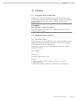
Page 51: ...not be accepted for repair or disposal 13 2 Disposing of Device and Parts 13 2 1 Information on Disposal The device and the accessories do not belong in your regular household waste since they are mad...

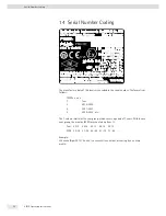
Page 52: ...allation and maintenance see control drawing 2003809 Pour installation et maintenance voir le No 2003809 du diagramme de contr le 2003809 The manufacture date of this device is encoded in the serial n...

Page 53: ...se EMC requirements Part 1 General Requirements Interference resistance Basic requirements Transient emissions Class B Suitable for use in residential areas and areas that are connected to a low volta...

Page 54: ...ificate Model specific Technical Data Specification Unit Value Accuracy class II Type PMA EV Weighing capacity max g 7500 Weighing capacity min g 5 Scale interval d g 0 1 Verification scale interval e...

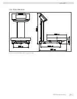
Page 55: ...VIS1X Operating Instructions 55 Technical Data 15 4 Device Dimensions Fig 1 Device dimensions PMA Vision VIS1X information in mm...

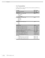
Page 56: ...USB YAK03 India Korea China Ex link converter YCO17 Z Link cable from converter to scale 10 m YCC01 0052M10 Link cable from converter to scale 20 m YCC01 0052M20 Link cable from converter to scale 30...

Page 57: ...or to contact a local representative please visit the Sartorius website www sartorius com 18 Conformity Approvals 18 1 EU Declaration of Conformity The attached Declaration of Conformity hereby confir...

Page 58: ...58 VIS1X Operating Instructions Conformity Approvals...

Page 59: ...ect the power supply or make sure that there is no potentially explosive atmosphere or any other explosion hazard in the surrounding area 8 If the equipment does not operate properly unplug it immedia...

Page 60: ...has been found to comply with the Essential Health and Safety Requirements relating to the design and construction of equipment intended for use in potentially explosive atmospheres given in Annex II...

Page 61: ...the YCO16 Z Ex Link Converter shall be connected together using a potential equalisation conductor with a cross sectional area of at least 4 mm2 3 The CAT6 cable used between the PMA Vision and the Y...

Page 62: ...IN ITS ENTIRETY AND WITHOUT CHANGE FM Approvals Ltd 1 Windsor Dials Windsor Berkshire UK SL4 1RS T 44 0 1753 750 000 F 44 0 1753 868 700 E mail atex fmapprovals com www fmapprovals com F ATEX 020 Apr...

Page 63: ...ipment has been found to comply with the Essential Health and Safety Requirements relating to the design and construction of equipment intended for use in potentially explosive atmospheres given in An...

Page 64: ...cted together using a potential equalisation conductor with a cross sectional area of at least 4 mm2 3 The CAT6 cable used between the PMA Vision and the YCO16 Z Ex Link Converter shall be obtained fr...

Page 65: ...the display unit must be prevented against damage and stress caused by strain 11 Prior to opening the equipment disconnect the power supply or make sure that there is no potentially explosive atmosph...

Page 66: ...nder certain extreme conditions The user shall ensure that the equipment is not installed in a location where it may be subjected to external conditions that might cause a build up of electrostatic ch...

Page 67: ...at least 4 mm2 3 The CAT6 cable used between the PMA Vision VIS1Y and the YCO16 Z Ex Link Converter shall be Equipment Ratings PMA Vision VIS1X Intrinsically Safe for Class I Division 1 Groups C and...

Page 68: ...en found to comply with the following Approval Standards and other documents FM Class 3600 2011 FM Class 3610 2010 FM Class 3611 2004 FM Class 3810 2005 ANSI ISA 60079 0 2013 ANSI ISA 60079 11 2014 Or...

Page 69: ...charges under certain extreme conditions The user shall ensure that the equipment is not installed in a location where it may be subjected to external conditions that might cause a build up of electro...

Page 70: ...at least 4 mm2 3 The CAT6 cable used between the PMA Vision VIS1Y and the YCO16 Z Ex Link Converter shall be Equipment Ratings PMA Vision VIS1X Intrinsically Safe for Class I Division 1 Groups C and...

Page 71: ...the following Approval Standards and other documents CSA C22 2 No 0 4 2013 CSA C22 2 No 157 1992 R2012 CSA C22 2 No 213 1987 R2013 CAN CSA C22 2 No 60079 0 2011 CAN CSA C22 2 No 60079 11 2014 CAN CSA...

Page 72: ...72 VIS1X Operating Instructions Conformity Approvals...

Page 73: ...VIS1X Operating Instructions 73 Conformity Approvals...

Page 74: ...74 VIS1X Operating Instructions Conformity Approvals...

Page 75: ...VIS1X Operating Instructions 75 Conformity Approvals 18 3 EU Type Examination Certificate Verified Models...

Page 76: ...y Marcas Etichette e Sigilli Typ Waage Type weighing instrument Type d instrument de pesage Tipo del instrumento de pesaje Tipo di strumento per pesare PMA EV PMA HD EG Baumusterpr fbescheinigung EC...

Page 77: ...e Dispositif indicateur Dispositivo indicador Dispositivo di visualizzazione Metrologische Daten Max Min e und wenn vorhanden d Metrological data Max Min e and if existent d Donn es m trologiques Max...

Page 78: ...orms are used to facilitate legibility in these instructions and always simultaneously denote the other gender as well Copyright notice This instruction manual including all of its components is prote...

Reviews: