11
OPERATION PRINCIPLE FOR AUTOMATIC FUEL DELIVERY SYSTEM:
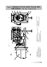
The boiler operates using a set consisting of:
• a fuel feeder with dual auger and transfer duct,
• blow furnace equipped with the moving grate,
• fan supplying air to the furnace;
• and an electronic temperature regulator – controller.
The fuel is transported from the fuel reservoir into the furnace chamber using
the feed fuel mechanism fuel with two distribution pipes (two transport augers dri-
ven by an electric motor) separated with a transfer duct providing distance betwe-
en. This solution provides secure transport of biomass, eliminating the need for
additional protection against uncontrolled retraction of fire into the fuel reservoir.
For safety reasons the gate closing the fuel reservoir during the combustion of
biomass in the burner must be sealed. The feeding mechanism consists of gear
motor that drivers the fuel feeding system by means of sprockets and a chain. The
feeder drive is under the safety cover. The fuel feeding mechanism – transport au-
gers are located in the closed isolating-and-guiding pipe. The biomass furnace is
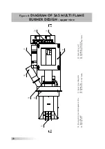
installed in the combustion chamber. It is possible to remove the feed mechanism
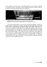
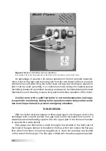
to periodic cleaning (Fig. 8) – mounting screws, sealing cord.
Biomass is supplied to the furnace chamber, where the automatic combustion
process is performed using the heater (electrical burner). The device is cooled by
a stream of air coming from the air duct. After reaching the preset temperature,
the automatic fuel ignition and fire support system enables the boiler the possibi-
lity of efficient operation even with low power thermal demand (possibility of con-
tinuous operation with domestic hot water reservoir during the summer period).
A characteristic feature of the SAS MULTI FLAME burner is an automatic, highly-
-effective and self-cleaning furnace burning exactly the portion of fuel necessary
to obtain the value set by the user on the temperature controller.
The burner is provided with a self cleaning furnace fitted with moving grates,
whose cyclic movement enables dropping the biomass ash and slag, ensuring
furnace purity over a long period of time.
The furnace elements (housing, moving grate, furnace grate, mounting plate)
exposed to high temperatures are made of stainless steel heat-proof sheet. Over
the furnace chamber there is a ceramic shape, which further protects the furnace
housing and causes reburning of unburned parts of flammable fuel. The burner
mounting plate is lined with a thermal insulation protecting fuel feeding mecha-
nism from heat.
Air for combustion is supplied by the fan driven by the electric motor and
connected to the furnace using an air-blowing duct. Part of the air is led under the
furnace grate, and the rest is blown directly into the combustion zone through the
distribution holes located on the sides of the furnace. The proper – depending on
the type of fuel burned – air flow is delivered by the blowing fan controlled by the
boiler controller.

