13
with a cylinder, the mixer can be controlled directly from the boiler controlled.
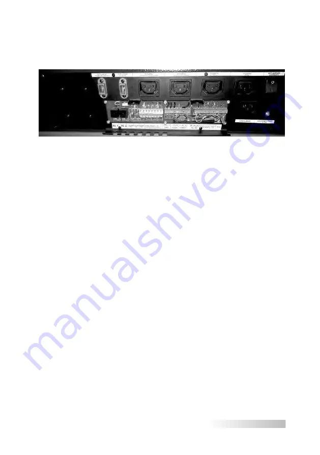
Connection points for circulatory pumps, temperature sensors and the mixer are
located on the boiler side wall (see Fig. 2 and Fig. 6).
The control unit (see Fig. 3, Fig. 6) of the burner automatically controls the
heater and the mechanism of furnace cleaning with the positioning sensor (hall
effect sensor). The temperature regulator mounted on the boiler controls the blo-
wing fan, fuel feeding mechanism and the feeder temperature sensor. The co-
operation between the controller (Fig. 6 item 39) of the feeder SAS MULTI FLAME
type, the master boiler controller (Fig. 6 item 28) is possible thanks to the wired
RS communication system. The control unit has the power cord, main switch and
a fuse. If there is no power supply to the control unit, the regulator displays “No
communication with M1” message and emits the audible alarm. An efficiently
working boiler furnace burns the amount of fuel necessary to maintain the tempe-
rature set on the controller by the user.
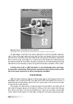
Figure 2
Connection terminal strip supplying control equipment
(An example of the power strip depending on the model of the controller mounted on the boiler)

